Japan
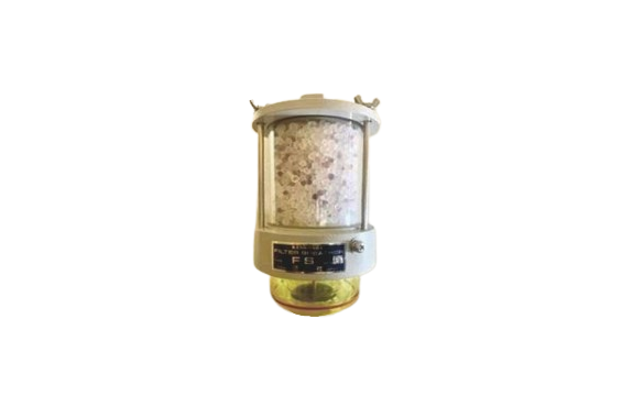
Kenkosha FPz/FGz Type Air Breather
Product Made In Japan
Model : FPz/FGz Type
Features
Filter breathers are attached to the ventilation pipes coming out of the top of transformers, oil-filled equipment, and insulated oil storage tanks to protect the inside of the equipment.
- The adsorbent and filter remove some moisture and fine floating particles from the incoming air, as well as through the insulating oil.
- Furthermore, the desiccant silica gel (except for FO type) removes almost all moisture, preventing rust inside the equipment and degradation of the oil.
- The oil pots for the FM, FP, FG types are made of large glass, and the inner cylinders are made of acrylic. For the FO, FS types, the oil pots and inner cylinders are acrylic, allowing for easy confirmation of even minor breathing actions, and there is less scattering of oil from the oil pots, making maintenance easy.
- The silica gel used is a mix of 30% blue and 70% white. There are also silica gels that do not use cobalt chloride. Caution: Ensure the minimum installation height above the ground is over 60cm, and do not install it in high places where people pass under the breather.
Specifications
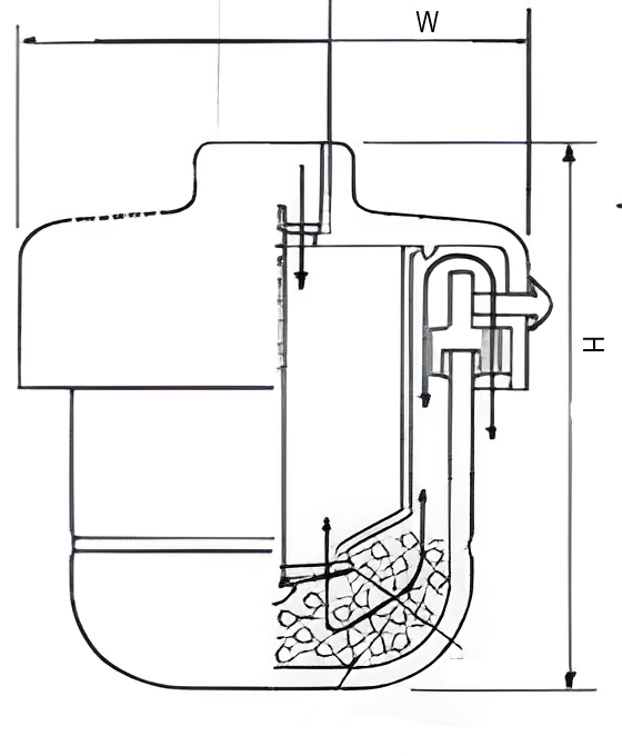
| Breather | Dimensions (mm) | Capacity of the desiccant | Connection method PF thread Flange | Standard for Transformers | ||
|---|---|---|---|---|---|---|
| Shape , Name | Height x Width | L | Kg | Oil quantity | Total amount | |
| L | L/min | |||||
| F0 | 103×0101 | – | – | PF 1/2 | 300 | 2 |
| FS | 200×0101 | 0.3 | 0.22 | PF1/2. FL | 500 | 2 |
| FS4 | 258×0101 | 0.53 | 0.4 | : : | 940 | 2 |
| FM | 290×0121 | 0.85 | 0.65 | PF 3/4 | 1,500 | 7 |
| Fp 1 | 345×0115 | 1.3 | 1.0 | PF 3/4, FL with flange type A Example: FP2A-G1 G1-15A G3-25A | 2,350 | 12 |
| FP2 | 480×0115 | 2.6 | 2.0 | 4,700 | 12 | |
| FP4 | 5700145 | 5.4 | 4.0 | 9,400 | 12 | |
| FG12 | 678×170 | 12 | 9.0 | FL | 21,000 | 16 |
| FPz 1 | 359×0115 | 1.3 | 1.0 | PF3/4, FL | 2,350 | 12 |
| FPZ 2 | 494×0115 | 2.7 | 2.0 | : : | 4,700 | 12 |
| FPZ 4 | 572×0145 | 5.4 | 4.0 | : | 9,400 | 12 |
| FGz 12 | 672×170 | 12 | 9.0 | FL | 21,000 | 16 |
| FGz 18 | 766×195 | 18 | 13 | Example: FGZ18-G1 G1-20A G2-25A | 32,000 | 28 |
| FGz 20k | 787×243 | 26.7 | 20 | 50,000 | 50 | |
| FGz 6SS | 605×145 | 6 | 4.5 | Tank: SUS304 and stainless steel FGz12ss.FGz20ss^ | 28 | |
| FGzisss | 815×195 | 18 | 13 | 80 | ||
| FU with flange connection | |||||
Proper Selection of Breathers
Breathers are selected from the table to the left based on the oil volume and maximum ventilation volume. However, when selecting, please consider:
- High humidity locations.
- Situations with high breathing frequency.
- For oil water-cooled transformers and oil tanks with large ventilation volumes, choose the type of device that has the optimal amount of silica gel and maximum ventilation volume according to the usage conditions. If the ventilation volume exceeds the capacity, oil from the oil pot may scatter. If the maximum ventilation volume exceeds 16 L/min or in environments with a lot of floating particles and 12 L/min or more, where FGz18 is not adopted, please conduct maintenance every two months

