KOGANEI CORPORATION
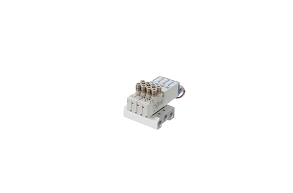
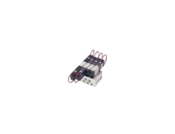
Koganei Solenoid Valve F10 Monoblock Manifold Direct Piping
Manufacturer: KOGANEI CORPORATION
Features
This product is designed for cylinder bore sizes ranging from 20 to 40 mm (1.575 to 3.150 in.) with a compact 10 mm (0.394 in.) valve width. Moreover, it features a direct piping type manifold, offering exceptional cost performance for efficient system integration.
Specifications
| Basic Model | F10T0 F10T1 F10T2 | F10T3 F10T4 F10T5 | F10TA F10TB F10TC | F10T0G F10T1G F10T2G | F10T3G F10T4G F10T5G | F10T0V F10T1V F10T2V | F10T3V | |
|---|---|---|---|---|---|---|---|---|
| Media | Air | |||||||
| Operation Type | Internal pilot type | External pilot type (for positive pressure) | External pilot type (for vacuum) | |||||
| Flow rate characteristics | Sonic conductance C dm³/s(bar) | 0.97 | 0.93 | 0.75 | 0.97 | 0.93 | 0.97 | 0.93 |
| Effective Area | 4.8 (0.27) | 4.6 (0.25) | 3.7 (0.21) | 4.8 (0.27) | 4.6 (0.25) | 4.8 (0.27) | 4.6 (0.25) | |
| Port Size | M5 × 0.8, 10-32UNF, dual use fitting for φ6 and φ8, Rc1/8, NPT1/8 | |||||||
| Lubrication | Not Required | |||||||
| Operating Pressure Range | Main valve | 0.2–0.7 MPa [29–102 psi.] | 0–0.7 MPa [0–102 psi.] Note4 | −100 kPa to 0.15 MPa [−29.53 in.Hg to 22 psi.] | ||||
| External pilot | — | 0.2–0.7 MPa [29–102 psi.] Note4 | 0.2–0.7 MPa [29–102 psi.] | |||||
| Proof Pressure | 1.05 MPa [152 psi.] | |||||||
| Response Time | 12VDC, 24VDC | 15/15 (20) | 15/20 (25) | 15/20 (25) | 15/15 (20) | 15/20 (25) | 15/15 (20) | 15/20 (25) |
| 100VAC | 15/15 | 15/20 | — | 15/15 | 15/20 | 15/15 | 15/20 | |
| Maximum Operating Frequency | 5 | |||||||
| Minimum Time to Energize for Self Holding | 50 | — | 50 | — | 50 | — | ||
| Operating temperature range (atmosphere and media) °C [°F] | 5–50 [41–122] | |||||||
| Shock Resistance | 294.2 [30] | |||||||
| Mounting Direction | Any | |||||||
| Item | 12VDC | 24VDC | 24VDC (Low-current type) | 100VAC | 120VAC |
|---|---|---|---|---|---|
| Voltage range | 10.8–13.2 (12 ±10%) | 21.6–26.4 (24 ±10%) | 21.6–26.4 (24 ±10%) | 90–110 (100 ±10%) | 108–132 (120 ±10%) |
| Rated frequency | — | — | — | 50 | 60 |
| Current (when rated voltage is applied) | 33 mA (r.m.s.) | 17 mA (r.m.s.) | 8 mA (r.m.s.) | 8 | 8 |
| Power consumption | 0.4 W | 0.4 W | 0.8 VA | 0.8 VA | 1 VA |
| Starting current | — | — | — | 17 | 17 |
| Starting time (standard) | — | — | — | 70 ms | 70 ms |
| Allowable leakage current | 2.0 | 1.0 | 1.0 | 1.0 | 1.0 |
| Type of insulation | Type B | Type B | Type B | Type B | Type B |
| Insulation resistance | 100 MΩ | 100 MΩ | 100 MΩ | 100 MΩ | 100 MΩ |
| Color of LED indicator | 14 (SA): Red 12 (SB): Green | 14 (SA): Red 12 (SB): Green | 14 (SA): Red 12 (SB): Green | 14 (SA): Red 12 (SB): Green | 14 (SA): Red 12 (SB): Green |
| Surge suppression | Surge absorption transistor | Flywheel diode | Flywheel diode | Bridge diode | Bridge diode |
Related Products
REQUEST QUOTATION

PAYMENT

LINK


