Kyowa Electronic Instruments Co., Ltd.
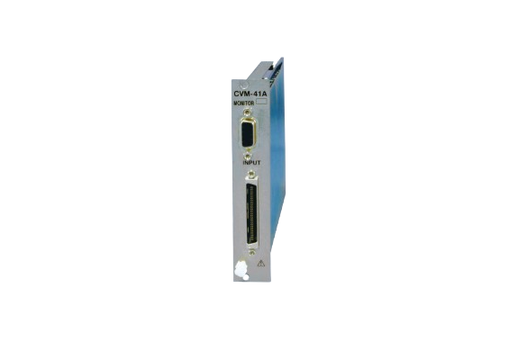
Kyowa CVM-41A Strain/Voltage/Acceleration Measurement Card EDX Series Conditioner Card

Manufacturer: Kyowa Electronic Instruments Co., Ltd.
Model: CVM-41A Strain/Voltage/Acceleration
Conditioner card for EDX-200A and EDX-5000A
Feature of CVM-41A Strain/Voltage/Acceleration
You can select according to the application. In addition to strain, voltage, acceleration, and temperature measurements, CAN data is also supported. Furthermore, noise-resistant isolation amplifier cards are available. Additionally, dynamic strain measurement cards are offered, enhancing the versatility and utility of the system.
Specification
| Strain measurement | Voltage measurement | Acceleration measurement (Piezoelectric) | |
|---|---|---|---|
| Applicable Recorders | EDX-100A, EDX-200A, EDX-5000A | ||
| Channels | 8 | ||
| Measuring Targets | Strain gages, strain-gage transducers * For strain measurement, use bridge boxes | Voltage Voltage-output sensors | Piezoelectric accelerometers (Built-in amplifier) |
| Input Modes | [Strain measurement] Balanced differential input | Balanced differential input *When using the Conversion Adapter FV-1A, this becomes unbalanced input *Common mode input voltage range ±20 VDC, absolute input voltage range ±50 V | Unbalanced input *Conversion Adapter FV-1A usage possible |
| Input Impedance | – | 1 MΩ + 1 MΩ Within ±10% *When using Conversion Adapter FV-1A (At unbalanced input), within 1 MΩ ±10% | – |
| Bridge Excitation or Power Supply to Sensors | Const. voltage output BV2V: 2 VDC BV5V: 5 VDC BV10V: 10 VDC | Const. voltage output BV2V: 2 VDC (±1 V) BV5V: 5 VDC (±2.5 V) BV10V: 10 VDC (±5 V) or OFF 20 mA/channels or less | Const. current output (Approx. 4 mA) (Excitation voltage: Approx. 23 VDC, Load: 1 kΩ or less) |
| *Each channel settable. The max. channels of CVM-41A in EDX-100A is 3 times of units of CVM | |||
| Gage Factor | 2.00 fixed | – | – |
| Compatible Bridge Resistance | BV2V: 120 to 1000 Ω BV5V: 350 to 1000 Ω BV10V: 500 to 1000 Ω | – | – |
| Balance Operation Settings(Zero suppression) | ——-Autobalance enabled Cancel the unbalanced bridge portion in the analog circuit, and zero the measurement value. ——-Autobalance disabled Do not cancel the unbalanced bridge portion (The initial unbalanced value in the bridge circuit can be confirmed) | ——-Zero suppression enabled Cancel the input voltage in the analog circuit, and zero the measurement value ——-Zero suppression disabled Do not cancel the input voltage in the analog circuit (Display the input voltage as is) | – |
| Balance Adjustment Range | BV2V: Resistance ±10% (±50k ×10-6 strain) BV5V: Resistance ±4% (±20k ×10-6 strain) BV10V: Resistance ±2% (±10k ×10-6 strain) | ±5 V | – |
| Measuring Range | BV2V: 5 k, 10 k, 20 k, 50 k, 100 k, 200 k, 500 k ×10-6 strain BV5V: 5 k, 10 k, 20 k, 50 k, 100 k, 200 k ×10-6 strain BV10V: 2 k, 5 k, 10 k, 20 k, 50 k, 100 k ×10-6 strain | 1, 2, 5, 10, 20, and 50 V | 100, 200, 500, 1000, 2000, and 5000 mV |
| Range Accuracy | Within ±0.2%FS | Within ±1.0%FS | |
| Nonlinearity | Within ±0.1%FS | Within ±0.2%FS | |
| Calibration (CAL)SHUNT CAL | ±100% and ±50% of each range and SHUNT *When SHUNT CAL has 350 Ω load connected, approx. 257 ×10-6 strain output. | ±100% and ±50% of each range | ±100% and ±50% of each range |
| Frequency Response | DC coupling: DC to 5 kHz, deviation +1dB, -3dB AC coupling: 0.2, 1 Hz to 5 kHz (See the HPF.) | 0.5 Hz to 5 kHz, deviation +1dB, -3dB | |
| LPF | Transfer characteristics : 5 Butterworth type Cutoff frequencies : 30, 100, 300, 1 k, 3 k Hz, FLAT and AUTO *With AUTO settings, the cutoff frequency is set to 1/4 of the sampling frequency. Cutoff accuracy : Within -3 ±1 dB Attenuation : -30 (+3, -7) dB /oct. | ||
| HPF | Cutoff frequencies: 0.2 Hz, 1 Hz Attenuation: -6 dB/oct. | Cutoff frequencies: 0.2 Hz, 1 Hz Attenuation: -6 dB/oct. | – |
| Resolution | 24 bits *When installed in EDX-100A, its resolution becomes 16 bits. | ||
| Distortion Rate | – | – | 1% or less |
| Monitor Output | Accuracy: Within ±5 V ±0.5% (With ±FS) Nonlinearity: Within ±0.5%FS | ||
| Dimensions | 22 W x 119 H x 213 D mm (Excluding protrusions) | ||
| Weight | Approx. 400 g | ||
| TEDS | Reads information from TEDS-installed sensors. | ||
| Compliance | Directive 2014/30/EU (EMC) Directive 2011/65/EU, (EU) 2015/863 (10 restricted substances) (RoHS) | ||
| Standard Accessories | 2 cross recessed binding head screw M3x6 |
|---|---|
| Optional Accessories | CCA input cable U-111 CVM input cable U-121 to U-123 CVM input integrated cable N-121 Integrated output cable U-62 Conversion adapter FV-1A Voltage input box VI-8A (-T) Bridge box for quarter bridge system DBS-120B-8 (C) (T) DBS-350B-8 (C) (T) One-touch type bridge box DBV-120A-8 (C) DBV-350A-8 (C) |
REQUEST QUOTATION

PAYMENT

LINK


