Japan, Magnescale
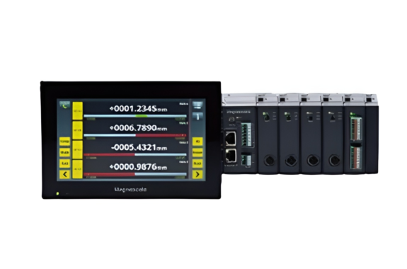
Magnescale LT80/MG80-MA/ MG80-CM Data Acquisition System
Made in Japan
Manufacturer: Magnescale Co., Ltd.
Model: LT80/MG80-MA/ MG80-CM
Features
LT80 Clear and easy to use HMI functions
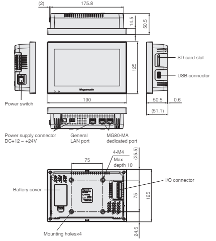
- 7-inch touch screen LCD display
- Multiple measurement modes (current value, MIN, MAX P-P, ADD/SUB.) Can be used for defective part identification, trend management, part sorting and tolerance judgement by using 2 or 4 state comparator function
- Displays I/O status
- Three data storage and parameter setting options (SD card, USB, and Ethernet)
- Multiligual support (Japanese, English, German)
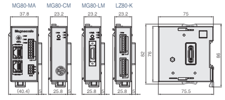
MG80 Expandable multi-axis measurement module system
- Connect up to 32 Magnescale DK- or DT-series gauges (via MT adaptor)
- DIN rail mount for easy installation (MG80 and LZ80)
- High speed latch (via MG80-LM latch module)
- -Synchronized angle and position measurement is available*1 by connecting a linear or rotary encoder*2
- *1 16 axes max.
- *2 Requires A/B Quadrature encoder signal (EIA-422 compliant).
- -Latching data with specific angles or distances can be saved to the LT80.
LZ80 I/O module
- Equipped with 8 inputs and 8 outputs
- Functions can be assigned freely from LT80
Up to two MG80 I/O modules can be connected to one MG80-MA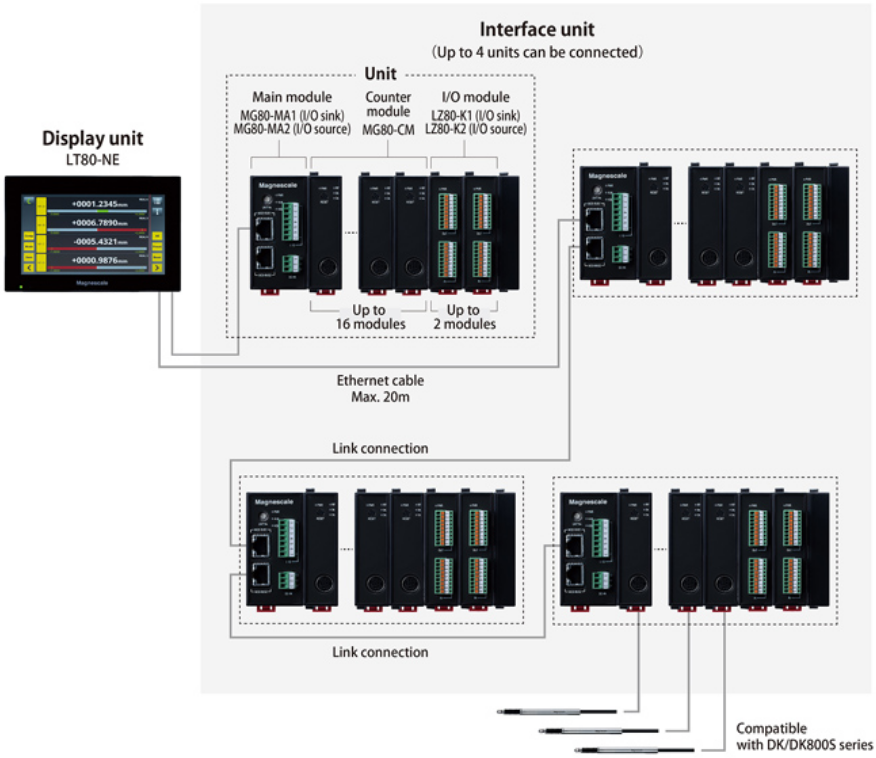
Specifications
| Display unit | |||||
|---|---|---|---|---|---|
| Model | LT80-NE | ||||
| Power consumption | 14W or less | ||||
| Maximum connectable units | 4 units of MG80-MA*1 | ||||
| Measurement screen | Measurement display | Display measurement values of 2, 4, 6, 8 or 16 channels, Alarm display, Comparator group, Measurement mode, Measurement bar graph, Reset, Preset | |||
| I/O information | I/O condition monitoring (All I/O of display unit and main module) | ||||
| Setting menu | Measuring unit setting | Resolution, direction, with or without reference point connected to MG80-CM | |||
| Display setting | Set number of channels to display: 2, 4, 8 or 16 channels | ||||
| Measurement mode | Measurement mode setting of each channel (current, MAX, MIN, P-P) | ||||
| Comparator value setting | 8 groups with 2 stages, or 8 groups with 4 stages per channel Default setting of each CH | ||||
| I/O setting | I/O function assignments of LT80-NE, I/O function assignments of connected LZ80-K, Reference point detection, Reset, Preset, Comparator output, Alarm, Reference point passed, Each channel address, Change measurement mode | ||||
| Calculation | Maximum of 16 combinations of add/subtract calculations per MG80-MA module | ||||
| Maintenance display | Main body information, Service usage (Software update for LT80 and MG80) | ||||
| General I/O | Photo coupler insulated 4 inputs and 4 outputs (functions set on main unit) | ||||
| Interface connector | For control: RJ45x1 (shielding compatible) For data: RJ45x2 (shielding compatible) SD card slot x 1, USB A connector x 1 | ||||
| Power input connector | Terminal block x 1 (3 poles), DC jack (EIAJ4) x 1 | ||||
| *1 When using LINK function of MG80-MA dedicated port and MG80-MA | |||||
Main module | ||||
|---|---|---|---|---|
| Model | MG80-MA1/MG80-MA2 | |||
| Power consumption | 2.4W or less | |||
| Maximum connectable units | 16 MG80-CM units, 2 LZ80-K units*1 | |||
| I/O | 7-pole connector Photo coupler insulated 4 input, 1 output MG80-MA1: Current sinking type MG80-MA2: Current source type | |||
| Interface connector | For data: RJ45 x 2 (sheilding compatible) | |||
| Communication protocol | 100BASE-TX | |||
| Transmission speed | 100 Mbit/s | |||
| Maximum cable length | 20m (CAT5e shielding type recommended*2) | |||
| Setting menu | Rotary switch for setting unit number | |||
| *1 Per each MG80-MA1/MA2. Total system maximum: 4 MG80-MA1/MA2 units, 32 MG80-CM units, 8 LZ80-K units. *2 The customer must provide the communication cables. | ||||
Counter module | ||
|---|---|---|
| Model | MG80-CM | |
| Power consumption | 2.0W or less (Measuring unit excluded) | |
| Compatible measuring units | DK series, DT series (via MT) | |
| Alarm | Frequency response exceeded, Measuring unit not connected, Cable breakage | |
Latch module | ||
|---|---|---|
| Model | MG80-LM | |
| Data refresh rates | 100µs (measured data acquisition only) 400µs (Applies to all functions such as reference point, calculations, comparator function, Max, Min and P-P) | |
| Power consumption | 2.0W or less (Encoder excluded) | |
| Encoder signal input | A/B/Z (reference point) Voltage differential line receiver (EIA-422 compliant) | |
| A / B signal input minimum phase difference | 50ns | |
| Power supply for connected encoder | DC5V 500mA (Max) | |
| Alarm | Input response frequency exceeded, encoder not connected, Cable breakage | |
| I/O module | ||
|---|---|---|
| Model | LZ80-K1/LZ80-K2 | |
| Power consumption | 2.0W or less | |
| I/O | 9-pole connector × 2 Photo coupler insulated 8 input, 8 output LZ80-K1: Current Sink LZ80-K2: Current Source | |
| LT80/MG80/LZ80 | ||||
|---|---|---|---|---|
| Supply voltage | DC10.8~26.4V | |||
| Operating temperature/humidity range | 0 to +50℃ (No condensation) | |||
| Storage temperature/humidity range | −20 to +60℃ (20 to 90%RH) | |||
| *Please refer to the LT80 operation manual (Ver 1.04.00 or later) for details on the functions. | ||||
Related Products
-
Miyakawa B Type General Purpose Milling
-
OSC92GT500 Digital CO² Checker
-
Tohnichi QF/QFR Beam type Torque Wrench
-
Eagle Jack ED-160TC Hydraulic Bottle Jack
-
Ross Asia No. 2151B7001/2151B7002 Inline poppet valve with extended temperature range
-
Kitz EAE100/200-TE,TNE,TUE,UTE,TKSE Type EAE Electric Actuators/Class 10K* Bronze, Brass or Stainless Steel Ball Valves
REQUEST QUOTATION

PAYMENT

LINK


