Japan, Magnescale
Magnescale MG40 Interface
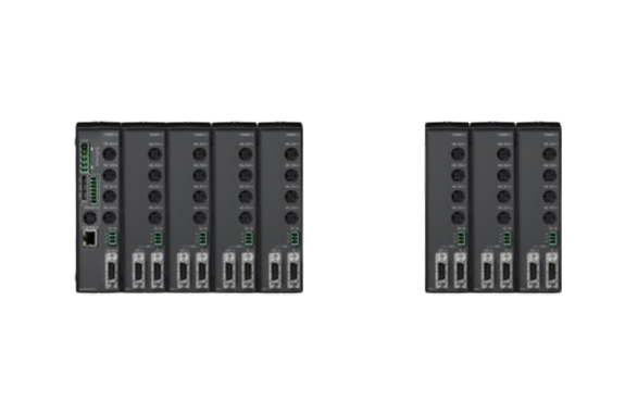
Made in Japan
Manufacturer: Magnescale Co., Ltd.
Model: MG40
Features
- High-speed and highly reliable communication shortens cycle times
- High-speed communication via Ethernet
- Communication error detection
- High-speed RISC processor dedicated to communication
- Our proprietary high-speed processor for multi-axis data processing
- Newly developed ASIC
- Quick and simple wiring connections
- Connection via a hub
- PLC connections
- Power supply
- Acquiring individual gauge information
- DIN rail mount and frontal connections
- Maximized system efficiency
- On the path to a revolution in quality
- High-speed measurements enable shorter cycle time
- Lower overall system costs
Specifications
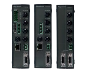
MG41-NC Series Specifications
Item Conditions Description Remarks No. of connectable measuring units Entire system 1 to 100 units (Connection disabled aft er connection of 101st unit.) Up to 24 connected MG42 hub units MG41 main unit 0 to 4 units MG42hub unit 0 to 4 units Connectable measuring units DK800S series, DK series Connection cable length Between MG41 main unit and MG42 hub unit, and between MG42 hub unit and MG42 hub unit : 0.5 m, 1 m, 2 m, 5 m, 10 m
Total cable length from MG41 main unit: Maximum 30 m (Maximum current: 4 A or less)Maximum resolution Settable output data resolution and display resolution Measuring units resolution (input resolution) 0.1 µm 0.1 µm 0.5 µm 1 µm 5 µm 10 µm 0.5 µm – 0.5 µm 1 µm 5 µm 10 µm Measuring unit data import capacity data transfer 10 Mbps Max. 10000 data/s (when 100 axes are connected) The data for one axis is counted as one data. Peak hold function Calculates the maximum, minimum, and P-P values for each axis (pause, latch, and start functions available) The system does not update the peak value while it is paused. During latching, the system does not update the output and display data, although it continues to update the internal data. Recalculation of peak value is started by start function. Output data Single axis Current value, maximum value, minimum value, and P-P value of each axis Addition and subtraction Current value, maximum value, minimum value, and P-P value of the two addition / subtraction axes Single axis calculation of an addition / subtraction axis is not possible. Conparetor function The system compares and measures the data from each axis (single axis, addition/subtraction axis) and outputs the result of the comparison, latching the comparator if necessary. Comparator setting values 2 values 4 values 8 values 16 values No. of setting value groups 16 groups 8 groups 4 groups 2 groups Ethernet 100Base-T (compliant with IEEE 802.3) 100 Mbps/10 Mbps/1 Mpbs (Auto-negotiation) command input, data output and parameter setting available Reset function Current value for each axis is reset (by command). Preset function Value is preset to the current value of each axis (by command). Datum point setting function You can set the datum point for each axis using a command. When master calibration function is not used Reference point function You can relocate the datum point of each axis using a reference point through a command. Master calibration function Reference point can be used to perform master calibration for each axis (by command). Measuring unit product information You can acquire the product information of the connected measuring unit through a command, which includes the product code, serial number, and manufacture date. Command/setting enabled or disabled for each communication line
Ethernet CC-Link Command Reset function ○ ○ Preset function ○ ○ Datum point setting function ○ ○ When master calibration function is not used Reference point function ○ ○ Master calibration function ○ ○ Comparator value setting ○ ○ Comparator group number setting ○ ○ Start ○ ○ Pause ○ ○ Latch ○ ○ Data output Current value・Peak value (all axis) ○ × Current value・Peak value (each unit) ○ ○ Comparator result ○ ○ Alarm (data transfer・measuring units) ○ ○ Software version ○ ○ Measuring unit product information ○ ○ Various settings Input resolution ○ ○ Display・output resolution ○ ○ Axis addition ○ ○ Comparator mode (2, 4, 8, or 16 values in 1 group) ○ ○ Power supplyPower supply voltage Terminal input DC12 to 24 V (11 to 26.4 V) Use a power supply with a current that is 4 A or higher. (Recommended: +24 V) (for every six MG42 hub units) Power consumption Note the connection conditions. System total : Max. current 4 A If the maximum current is exceeded, power can be supplied to a subsequent MG42 hub unit to facilitate connection. Power consumption breakdown for each unit
MG41 main unit : 4 W
MG42 hub unit : 1 W/unit
Measurement unit supply : 1 W/unitOperating temperature/humidity 0 to +50 °C (non condensing) Storage temperature/humidity -10 to +60 °C (20 to 90 %RH) Mass MG41 : 300 g MG42 : 250 g
Related Products
-
Kanetec KEZX-50100A Super Powerful Electromagnetic Chuck With T-Slots
-
Chiyoda Seiki GS-200H Series Medium Flow Self-powered Pressure Regulator (Primary pressure: 15.0 MPa or less/adjustment pressure 1.0 to 4.0 MPa, standard flow rate: 620 m3/h・Air)
-
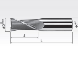
Okazaki Seiko MED2 MCO Square Endmill 2 Flutes (Regular Flute Length)
-
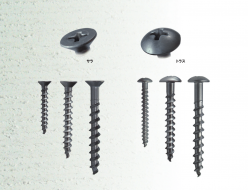
JPF ALinC Screw Fixed Anchor
-

Japan Life PF Insert (JL Insert Series)
-
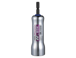
Vessel No.TA “GO-TAN” (Hard Forged) Mirror Socket


