Miyawaki
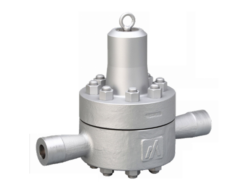
Miyawaki RE1 Direct Acting For Steam
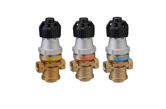
Manufacturer: MIYAWAKI Inc.
Model: RE1
Features
Self acting pressure reducing valve for steam
Automatic valve that reduces the steam supply pressure to a defined set pressure.
Pressure fluctuations on upstream side are followed by the downstream side.
No external energy required
Operating features of direct acting pressure reducing valves
Downstream pressure changes are detected in the detection chamber, and the degree of opening of the valve is directly adjusted to maintain the set pressure.
Compact and cost effective design
Can be installed in tight spaces thanks to its compact design (small/lightweight). Offers reliable operation, energy saving, and productivity improvement.
Superb durability
Control bellows with moren than … operating cycles offers outstanding durability. Protected by integrated strainer.
Easy handling
Pressure can easily adjusted by the topside handle.
Typical applications
Perfect for small to medium steam flows as present in laundries, F&B equipment, sterilizers and similar equipment.
Dimensions/Weight
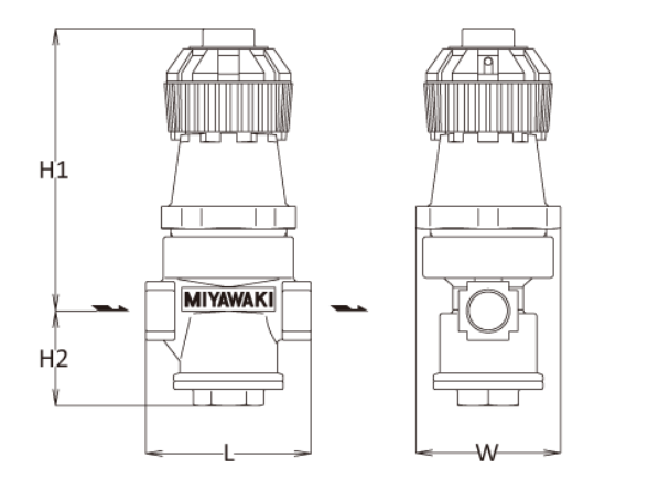
| Size | Dimensions (mm) | Dimensions (in) | Weight | |||||||
| L | H1 | H2 | W | L | H1 | H2 | W | (kg) | (lb) | |
| 1/2” | 80 | 137 | 46 | 65 | 3.2 | 5.4 | 1.8 | 2.6 | 1,4 | 3.1 |
| 3/4” | 90 | 3.5 | 1,6 | 3.5 | ||||||
| 1” | 105 | 144 | 58 | 4.1 | 5.7 | 2.3 | 1,9 | 4.2 | ||
Specifications
| Model | Connection | Max. operating pressure (PMO) | Max.operating pressure range | Control pressure range | Values | Max.pressure reduction ratio | Max. operating temperature (TMO) | Body material | ||||||
| Type | Size | (MPa) | (psig) | Primary side pressure (MPa) | Primary side pressure (psig) | Secondary side pressure (MPa) | Secondary side pressure (psig) | Cv | kvs | (℃) | (℉) | |||
| RE1 | Screwed Rc,NPT | 1/2” | 1,6 | 230 | 0,2 – 1,6 | 29 – 230 | 0,05 – 1,0 | 7.3 – 145 | 1,2 | 1,0 | 10:1 | 204 | 399 | Brass |
| 3/4” | 1,9 | 1,6 | ||||||||||||
| 1” | 3,2 | 2,8 | ||||||||||||
| RE1-2 | 1/2” | 1,0 | 145 | 0,2 – 1,0 | 29 – 145 | 0,02 – 0,2 | 2.9 – 29 | 1,9 | 1,6 | |||||
| 3/4” | 1,9 | 1,6 | ||||||||||||
| 1” | 2,1 | 1,8 | ||||||||||||
| RE1-4 | 1/2” | 1,0 | 145 | 0,2 – 1,0 | 29 – 145 | 0,05 – 0,4 | 7.3 – 58 | 1,2 | 1,0 | |||||
| 3/4” | 1,9 | 1,6 | ||||||||||||
| 1” | 3,2 | 2,8 | ||||||||||||
Recommended accessories: Y strainer / YM1 x1
Offset: RE1: 0.15MPa (21.8psig) or lower, RE1-2: 0.05MPa (7.3psig) or lower, RE1-4: 0,07MPa (10.2psig) or lower
Minimum differential pressure: 20% of the primary side
Lockup pressure: 0,03MPa (4.4psig) or lower
Capacity Chart (MPa)
RE1
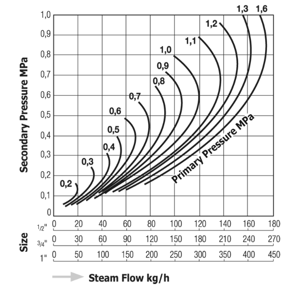
How to use this chart
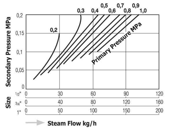
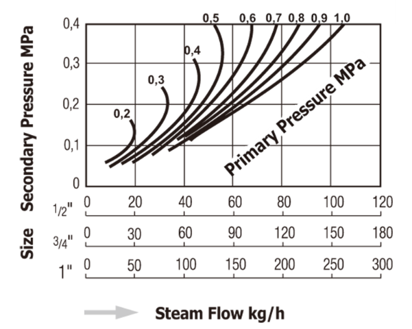
1. Find the point at which the upstream pressure and desired downstream pressure horizontal line intersect.
2. Trace a vertical line from the point where they intersect, and select for the smallest-nominal size where the required steam flow rate met.
*for downstream pressures from 0,4MPa (58psig) (4kgf/cm2・g) to 0,2MPa (29psig) (2kgf/cm2・g) or lower, use RE1-4 model. for downstream pressures from 0,2MPa (29psig) (2kgf/cm2・g) or lower with high flow rate, RE1-2 is recommended.
RE1-2
RE1-4
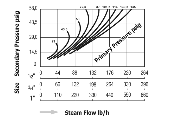
Capacity Chart(psig)
RE1
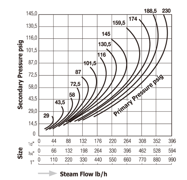
How to use this chart
1. Find the point at which the upstream pressure and desired downstream pressure horizontal line intersect.
2. Trace a vertical line from the point where they intersect, and select for the smallest-nominal size where the required steam flow rate meet.
*for downstream pressures from 0,4MPa (58psig) (4kgf/cm2・g) to 0,2MPa (29psig) (2kgf/cm2・g) or lower, use RE1-4 model. for downstream pressures from 0,2MPa (29psig) (2kgf/cm2・g) or lower with high flow rate, RE1-2 is recommended.
RE1-2
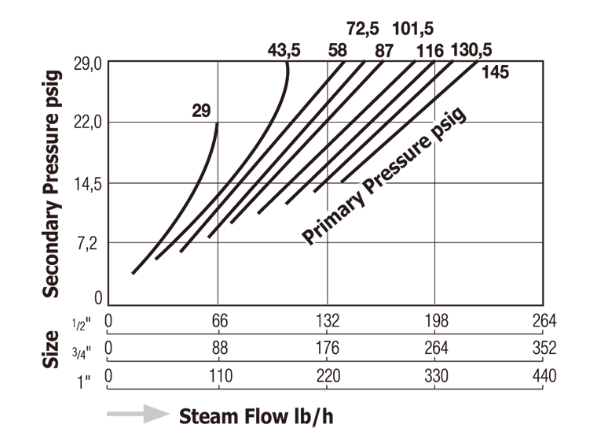
RE1-4
