Miyawaki
Miyawaki REH20-M Direct Acting For Steam
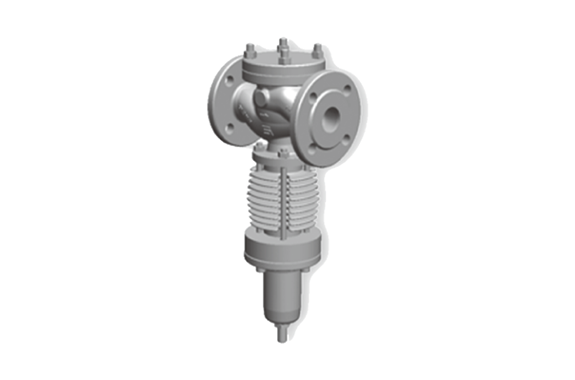
Manufacturer: MIYAWAKI Inc.
Model: REH20-M
Features
Self-acting pressure reducing valve for steam
This valve reduces the steam supply pressure to a defined outlet pressure and keeps it steady, even under downstream fluctuations . The valves needs no seperate energy source.
Operating features of direct acting pressure reducing valves
Pressure changes on the downstream side are detected in the detection chamber, and the degree of opening of the valve is directly adjusted to keep the pressure on the downstream side at set pressure.
Wide range of pressure reduction
Due to carfefully selected springs an outstanding reduction ratio of 25:1 is achieved.
Diaphram free design
The valve operates with an O-ring sealing and a piston design. Due to this design, no daiphragm and no external sensing line is required.
Superb durability
Highly durable and carefully selected components, a 360° free rotating, conical plug and the lack of a sensitive diaphragm ensure outstanding lifetime of this valve.
Options available
– additional pressure gauges
– tailored connections for special applications
– softsealing for leakage class VI
Typical applications
Perfect for all applications with medium to high steam flow or high reduction. In particuliar power plants, chemical and petrochemical process applications, ships, food and beverage plants, and other similar installations of of compact steam equipment.
Dimensions/Weight
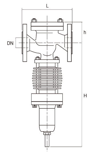
Size (DN) | Dimensions (mm) | Kvs Value | ||
| L | H | h | ||
| 15 | 210 | 410 | 82 | 1,8 |
| 20 | 230 | 66 | 3,2 | |
| 25 | 230 | 66 | 5,0 | |
| 32 | 260 | 81 | 7,9 | |
| 40 | 260 | 83 | 13,0 | |
| 50 | 300 | 586 | 100 | 20,0 |
| 65 | 340 | 615 | 113 | 34,0 |
| 80 | 380 | 733 | 140 | 51,0 |
| 100 | 430 | 762 | 154 | 80,0 |
Specifications
Cast steel
G17CrMo 5-5
(1.7357)
| PN63 | PN100 | |
| Max. design pressure (MPa) PMA | 6,3 | 10,0 |
| Max. design temperature (℃) TMA | 530 | 530 |
| Max. operating pressure (MPa) PMO | 5,7 | 8,4 |
| Max. operating temperature (℃) TMO | 530 | 530 |
| PN | Temperture ℃ | ||||||||||
| -10・・・+50 | 100 | 150 | 200 | 250 | 300 | 350 | 400 | 450 | 500 | 550 | |
| Pressure MPa | |||||||||||
| PN63 | 6,3 | 6,3 | 6,3 | 6,3 | 6,2 | 5,7 | 5,3 | 5,0 | 4,8 | 3,8 | 2,2 |
| PN100 | 10,0 | 10,0 | 10,0 | 10,0 | 9,8 | 9,1 | 8,4 | 8,0 | 7,6 | 6,1 | 3,5 |
Secondary pressure range | DN15-DN40 | DN50 | DN65 | DN80 | DN100 | DN125-DN200 |
| MPa | Spring number per size | |||||
| 0,05-0,1 | 9 | 28 | 27 | 38 | 37 | On request |
| 0,1-0,16 | 8 | 27 | 26 | 37 | 36 | |
| 0,16-0,25 | 7 | 26 | 25 | 36 | 35 | |
| 0,25-0,4 | 6 | 25 | 24 | 35 | 34 | |
| 0,4-0,63 | 5 | 24 | 23 | 34 | 33 | |
| 0,63-1,0 | 4 | 23 | 22 | 33 | 32 | |
| 1,0-1,6 | 3 | 22 | 21 | 32 | 32 | |
Secondary pressure ranges higher than 1,6 MPa and lower than 0,05 MPa on request available.
Capacity Chart
Tables of calculation for steam
RE20 (REH20, REC20)
RE20L (REH20L, REC20L)
How to select the size of a PRV correctly?
Check the operating data:
- Inlet pressure p₁
- Requested downstream pressure p₂
- Requested steam flow
Check the requested steam flow in the capacity chart on page 15. Select the necessary size of the PRV. Table 1 shows the maximum available steam flow in kg/h at a given inlet pressure, if the ratio between the requested downstream pressure p₂ and the inlet pressure p₁ is lower than 0.577 (critical flow). Pay attention that the steam pressure is shown as bar_abs!

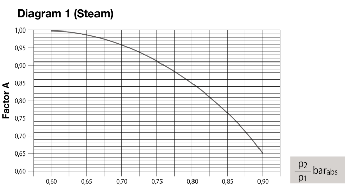
If the ratio between the downstream pressure p₂ and the inlet pressure p₁ is larger than 0.577 (non-critical flow), the available steam flow amount on the downstream side will be reduced. To get the maximum available downstream flow amount, the maximum steam flow from Table 1 must be multiplied with the calculation factor A. To get the Factor A see the Diagram 1.
Check if the requested steam flow matches the downstream side using Table 2 (page 16) for flows under 40 m/s. Choose the size based on barg pressure. If downstream piping is 1–2 sizes larger than the PRV inlet, you’re good. If the size difference is over 2, increase the PRV size. Keep the difference within 2 sizes!
Example of calculation
Operating data:
- p₁ = 9 barg = 10 bar_abs
p₂ = 6 barg = 7 bar_abs
Steam flow G = 1,100 kg/h - Search for the necessary size of the PRV in accordance with p₁.

- Table 1 shows 1,312 kg/h for size DN40 (1½”).
- bar_abs = 0.7 (i.e., larger than 0.577)
- Factor A acc. to Diagram 1 = 0.96
- Max. available steam flow G = 1,312 kg/h × 0.96 = 1,259 kg/h.
Steam flow in accordance with Table 2 at 6 barg = 1,720 kg/h for DN65.
Conclusion:
The PRV with an inlet size of DN40 and increase of the pipe size to DN65 at the downstream side will be suitable for a flow amount of 1,100 kg/h at the given pressures.
Capacity Chart
The Table 1 shows the maximum available steam flow amount of the pressure reducing valve at a given inlet pressure, if the ratio between the downstream pressure p₂ and the inlet pressure p₁ is lower than 0.577 (critical flow). Pay attention that the inlet steam pressure p₁ is shown as bar_abs.

Table 1
| P1 | Steam Flow per DN in kg/h | |||||||||||
| (bar abs) | 15 | 20 | 25 | 32 | 40 | 50 | 65 | 80 | 100 | 125 | 150 | 200 |
| 1,1 | 21 | 38 | 59 | 94 | 154 | 238 | 405 | 607 | 952 | 1.545 | 2.14 | 3.81 |
| 1,2 | 23 | 41 | 64 | 101 | 167 | 257 | 437 | 655 | 1.028 | 1.67 | 2.313 | 4.112 |
| 1,3 | 25 | 44 | 70 | 110 | 181 | 279 | 474 | 711 | 1.116 | 1.813 | 2.511 | 4.464 |
| 1,4 | 27 | 48 | 75 | 119 | 195 | 300 | 510 | 765 | 1.2 | 1.951 | 2.702 | 4.803 |
| 1,5 | 29 | 51 | 80 | 127 | 208 | 320 | 545 | 818 | 1.283 | 2.085 | 2.887 | 5.133 |
| 1,6 | 30 | 54 | 85 | 135 | 222 | 342 | 581 | 871 | 1.366 | 2.22 | 3.074 | 5.466 |
| 1,7 | 32 | 58 | 91 | 143 | 236 | 363 | 617 | 926 | 1.452 | 2.36 | 3.267 | 5.808 |
| 1,8 | 34 | 61 | 95 | 151 | 248 | 382 | 649 | 973 | 1.526 | 2.48 | 3.434 | 6.105 |
| 1,9 | 36 | 64 | 101 | 159 | 262 | 402 | 684 | 1.026 | 1.61 | 2.616 | 3.622 | 6.438 |
| 2,0 | 38 | 68 | 106 | 167 | 275 | 424 | 720 | 1.081 | 1.695 | 2.755 | 3.814 | 6.781 |
| 2,2 | 42 | 74 | 116 | 184 | 302 | 465 | 790 | 1.185 | 1.859 | 3.021 | 4.183 | 7.437 |
| 2,4 | 45 | 81 | 126 | 200 | 329 | 506 | 860 | 1.289 | 2.022 | 3.286 | 4.55 | 8.09 |
| 2,6 | 49 | 87 | 136 | 215 | 354 | 545 | 926 | 1.389 | 2.179 | 3.541 | 4.903 | 8.717 |
| 2,8 | 52 | 92 | 144 | 227 | 373 | 575 | 977 | 1.465 | 2.298 | 3.735 | 5.171 | 9.194 |
| 3,0 | 56 | 101 | 157 | 248 | 409 | 629 | 1.069 | 1.603 | 2.514 | 4.086 | 5.657 | 10.058 |
| 3,5 | 65 | 116 | 182 | 287 | 472 | 727 | 1.236 | 1.854 | 2.908 | 4.726 | 6.543 | 11.632 |
| 4,0 | 75 | 133 | 207 | 328 | 539 | 830 | 1.411 | 2.116 | 3.319 | 5.394 | 7.468 | 13.277 |
| 4,5 | 84 | 149 | 232 | 367 | 604 | 929 | 1.58 | 2.369 | 3.717 | 6.04 | 8.367 | 14.867 |
| 5,0 | 93 | 165 | 258 | 408 | 671 | 1.032 | 1.755 | 2.632 | 4.129 | 6.709 | 9.29 | 16.515 |
| 5,5 | 99 | 176 | 274 | 433 | 714 | 1.097 | 1.865 | 2.798 | 4.389 | 7.132 | 9.875 | 17.555 |
| 6,0 | 111 | 197 | 308 | 486 | 800 | 1.23 | 2.092 | 3.138 | 4.922 | 7.998 | 11.074 | 19.686 |
| 6,5 | 119 | 213 | 332 | 525 | 864 | 1.329 | 2.259 | 3.388 | 5.315 | 8.637 | 11.959 | 21.261 |
| 7,0 | 129 | 229 | 358 | 565 | 930 | 1.431 | 2.433 | 3.649 | 5.724 | 9.302 | 12.879 | 22.896 |
| 7,5 | 138 | 245 | 382 | 604 | 994 | 1.529 | 2.599 | 3.899 | 6.116 | 9.939 | 13.761 | 24.464 |
| 8,0 | 146 | 260 | 407 | 643 | 1.058 | 1.628 | 2.767 | 4.15 | 6.51 | 10.579 | 14.648 | 26.042 |
| 8,5 | 155 | 277 | 432 | 683 | 1.124 | 1.729 | 2.94 | 4.409 | 6.917 | 11.24 | 15.563 | 27.667 |
| 9,0 | 164 | 292 | 456 | 720 | 1.185 | 1.823 | 3.098 | 4.648 | 7.29 | 11.847 | 16.403 | 29.162 |
| 9,5 | 173 | 307 | 480 | 759 | 1.249 | 1.921 | 3.266 | 4.899 | 7.684 | 12.487 | 17.289 | 30.736 |
| 10,0 | 182 | 323 | 505 | 798 | 1.312 | 2.019 | 3.433 | 5.149 | 8.077 | 13.125 | 18.173 | 32.307 |
| 10,5 | 191 | 339 | 530 | 837 | 1.378 | 2.12 | 3.604 | 5.406 | 8.48 | 13.78 | 19.08 | 33.92 |
| 11,0 | 200 | 355 | 555 | 877 | 1.443 | 2.22 | 3.774 | 5.661 | 8.88 | 14.43 | 19.98 | 35.52 |
| 12,0 | 218 | 387 | 605 | 956 | 1.573 | 2.42 | 4.115 | 6.172 | 9.682 | 15.733 | 21.784 | 38.726 |
| 13,0 | 235 | 417 | 652 | 1.03 | 1.695 | 2.608 | 4.434 | 6.651 | 10.433 | 16.953 | 23.474 | 41.731 |
| 14,0 | 252 | 449 | 701 | 1.108 | 1.822 | 2.804 | 4.766 | 7.15 | 11.215 | 18.225 | 25.234 | 44.861 |
| 15,0 | 270 | 481 | 751 | 1.187 | 1.954 | 3.006 | 5.11 | 7.665 | 12.023 | 19.538 | 27.052 | 48.093 |
| 16,0 | 288 | 513 | 801 | 1.266 | 2.083 | 3.204 | 5.447 | 8.17 | 12.816 | 20.826 | 28.836 | 51.264 |
| 17,0 | 306 | 545 | 850 | 1.343 | 2.21 | 3.4 | 5.78 | 8.671 | 13.601 | 22.101 | 30.602 | 54.403 |
| 18,0 | 324 | 575 | 899 | 1.42 | 2.336 | 3.595 | 6.111 | 9.166 | 14.378 | 23.365 | 32.351 | 57.514 |
| 19,0 | 342 | 607 | 949 | 1.499 | 2.466 | 3.795 | 6.451 | 9.676 | 15.178 | 24.665 | 34.151 | 60.714 |
| 20,0 | 357 | 635 | 993 | 1.568 | 2.581 | 3.971 | 6.75 | 10.126 | 15.883 | 25.81 | 35.737 | 63.533 |
| 21,0 | 376 | 669 | 1.046 | 1.653 | 2.719 | 4.184 | 7.112 | 10.669 | 16.735 | 27.195 | 37.654 | 66.941 |
| 23,0 | 413 | 735 | 1.148 | 1.814 | 2.985 | 4.592 | 7.807 | 11.71 | 18.369 | 29.849 | 41.33 | 73.475 |
| 25,0 | 449 | 798 | 1.247 | 1.969 | 3.241 | 4.986 | 8.476 | 12.714 | 19.944 | 32.409 | 44.874 | 79.776 |
| 27,0 | 484 | 861 | 1.346 | 2.126 | 3.498 | 5.382 | 9.149 | 13.724 | 21.528 | 34.983 | 48.438 | 86.112 |
| 29,0 | 520 | 924 | 1.444 | 2.282 | 3.755 | 5.777 | 9.82 | 14.73 | 23.106 | 37.548 | 51.989 | 92.426 |
| 30,0 | 538 | 957 | 1.496 | 2.363 | 3.889 | 5.983 | 10.17 | 15.256 | 23.93 | 38.887 | 53.843 | 95.722 |
| 33,0 | 590 | 1.05 | 1.64 | 2.592 | 4.265 | 6.561 | 11.153 | 16.73 | 26.243 | 42.645 | 59.047 | 104.973 |
| Kvs | 1,8 | 3,2 | 5,0 | 7,9 | 13 | 20 | 34 | 51 | 80 | 130 | 180 | 320 |

Capacity Chart
The Table 2 shows the maximum available downstream steam flow amount of the pressure reducing valve at the requested downstream pressure p₂. Pay attention that the steam pressure p₂ is shown as barg.
Table 2
| P2 | Steam Flow per DN in kg/h | |||||||||||
| p2 (barg) | 15 | 20 | 25 | 32 | 40 | 50 | 65 | 80 | 100 | 125 | 150 | 200 |
| 0,1 | 16 | 29 | 45 | 73 | 115 | 179 | 303 | 460 | 715 | 1120 | 1610 | 2870 |
| 0,2 | 18 | 31 | 48 | 79 | 124 | 194 | 328 | 498 | 775 | 1215 | 1750 | 3110 |
| 0,3 | 19 | 34 | 52 | 85 | 134 | 209 | 353 | 535 | 835 | 1310 | 1880 | 3350 |
| 0,4 | 20 | 36 | 56 | 92 | 144 | 224 | 380 | 575 | 895 | 1405 | 2020 | 3590 |
| 0,5 | 22 | 39 | 60 | 99 | 154 | 239 | 405 | 615 | 955 | 1500 | 2170 | 3820 |
| 0,6 | 22 | 41 | 64 | 105 | 163 | 254 | 430 | 650 | 1015 | 1590 | 2290 | 4060 |
| 0,7 | 24 | 43 | 68 | 110 | 173 | 269 | 455 | 690 | 1075 | 1680 | 2420 | 4300 |
| 0,8 | 26 | 46 | 72 | 116 | 182 | 284 | 480 | 725 | 1135 | 1770 | 2550 | 4540 |
| 0,9 | 27 | 48 | 75 | 122 | 191 | 299 | 505 | 765 | 1195 | 1660 | 2680 | 4780 |
| 1,0 | 28 | 50 | 78 | 128 | 200 | 314 | 530 | 800 | 1250 | 1950 | 2820 | 5020 |
| 1,2 | 31 | 55 | 86 | 140 | 219 | 343 | 580 | 880 | 1360 | 2140 | 3080 | 5500 |
| 1,4 | 34 | 60 | 93 | 152 | 238 | 377 | 625 | 950 | 1480 | 2320 | 3350 | 5950 |
| 1,6 | 36 | 65 | 100 | 164 | 257 | 401 | 675 | 1025 | 1600 | 2500 | 3600 | 6420 |
| 1,8 | 39 | 69 | 107 | 176 | 275 | 430 | 725 | 1100 | 1720 | 2680 | 3850 | 6890 |
| 2,0 | 42 | 74 | 115 | 188 | 294 | 460 | 775 | 1180 | 1840 | 2870 | 4125 | 7360 |
| 2,5 | 48 | 84 | 132 | 217 | 338 | 530 | 890 | 1355 | 2120 | 3300 | 4750 | 8450 |
| 3,0 | 54 | 96 | 150 | 246 | 385 | 600 | 1010 | 1540 | 2400 | 3750 | 5400 | 9650 |
| 3,5 | 60 | 108 | 168 | 275 | 430 | 670 | 1130 | 1720 | 2680 | 4200 | 6050 | 10700 |
| 4,0 | 67 | 119 | 185 | 305 | 475 | 740 | 1250 | 1900 | 2960 | 4650 | 6650 | 11800 |
| 4,5 | 73 | 130 | 202 | 335 | 520 | 810 | 1370 | 2080 | 3240 | 5075 | 7300 | 13050 |
| 5,0 | 79 | 141 | 220 | 365 | 565 | 880 | 1490 | 2250 | 3520 | 5500 | 7900 | 14100 |
| 5,5 | 85 | 152 | 237 | 395 | 605 | 950 | 1600 | 2430 | 3800 | 5925 | 8500 | 15150 |
| 6,0 | 92 | 163 | 254 | 420 | 655 | 1020 | 1720 | 2610 | 4080 | 6350 | 9125 | 16300 |
| 6,5 | 98 | 174 | 271 | 445 | 695 | 1085 | 1840 | 2790 | 4360 | 6775 | 9750 | 17400 |
| 7,0 | 104 | 185 | 288 | 475 | 740 | 1160 | 1960 | 2970 | 4640 | 7200 | 10375 | 18500 |
| 7,5 | 110 | 196 | 305 | 500 | 785 | 1220 | 2070 | 3140 | 4900 | 7650 | 11000 | 19600 |
| 8,0 | 117 | 207 | 323 | 530 | 830 | 1290 | 2180 | 3320 | 5180 | 8100 | 11625 | 20700 |
| 8,5 | 123 | 218 | 341 | 560 | 875 | 1365 | 2300 | 3500 | 5450 | 8550 | 12250 | 21800 |
| 9,0 | 129 | 229 | 358 | 585 | 915 | 1430 | 2410 | 3670 | 5720 | 8975 | 12875 | 22900 |
| 9,5 | 135 | 240 | 375 | 615 | 960 | 1500 | 2530 | 3840 | 6000 | 9400 | 13500 | 24000 |
| 10,0 | 141 | 252 | 392 | 645 | 1000 | 1570 | 2650 | 4020 | 6270 | 9825 | 14125 | 25100 |
| 11,0 | 154 | 273 | 427 | 700 | 1090 | 1710 | 2880 | 4380 | 6800 | 10700 | 15300 | 27300 |
| 12,0 | 166 | 294 | 461 | 750 | 1180 | 1840 | 3100 | 4730 | 7300 | 11550 | 16500 | 29400 |
| 13,0 | 178 | 316 | 495 | 810 | 1270 | 1980 | 3340 | 5080 | 7850 | 12400 | 17750 | 31600 |
| 14,0 | 190 | 338 | 530 | 870 | 1355 | 2120 | 3570 | 5400 | 8400 | 13200 | 19000 | 33800 |
| 15,0 | 202 | 360 | 565 | 925 | 1440 | 2250 | 3800 | 5750 | 8950 | 14100 | 20300 | 36000 |
| 16,0 | 215 | 382 | 600 | 980 | 1530 | 2390 | 4030 | 6100 | 9550 | 15000 | 21600 | 38200 |
| 17,0 | 227 | 404 | 630 | 1020 | 1620 | 2530 | 4270 | 6450 | 10100 | 15900 | 22800 | 40400 |
| 18,0 | 240 | 427 | 665 | 1090 | 1710 | 2670 | 4500 | 6800 | 10650 | 16750 | 24000 | 42600 |
| 19,0 | 252 | 450 | 700 | 1145 | 1790 | 2800 | 4740 | 7150 | 11200 | 17600 | 25200 | 44800 |
| 20,0 | 263 | 473 | 730 | 1200 | 1870 | 2930 | 4950 | 7500 | 11750 | 18400 | 26500 | 47000 |
| 22,0 | 288 | 510 | 800 | 1310 | 2050 | 3200 | 5400 | 8200 | 12800 | 20000 | 28800 | 51000 |
| 24,0 | 312 | 555 | 870 | 1420 | 2220 | 3470 | 5850 | 8900 | 13900 | 21700 | 31200 | 55200 |
| 26,0 | 337 | 600 | 940 | 1530 | 2400 | 3750 | 6300 | 9600 | 15000 | 23400 | 33700 | 60400 |
| 28,0 | 362 | 645 | 1010 | 1650 | 2580 | 4020 | 6800 | 10300 | 16100 | 25100 | 36200 | 64600 |
| 30,0 | 387 | 690 | 1080 | 1770 | 2750 | 4300 | 7250 | 11000 | 17200 | 26900 | 38700 | 68800 |
| 32,0 | 413 | 735 | 1150 | 1890 | 2950 | 4600 | 7750 | 11800 | 18300 | 28800 | 41300 | 73500 |

