Japan, Nachi
NACHI SAW-G01 Valve
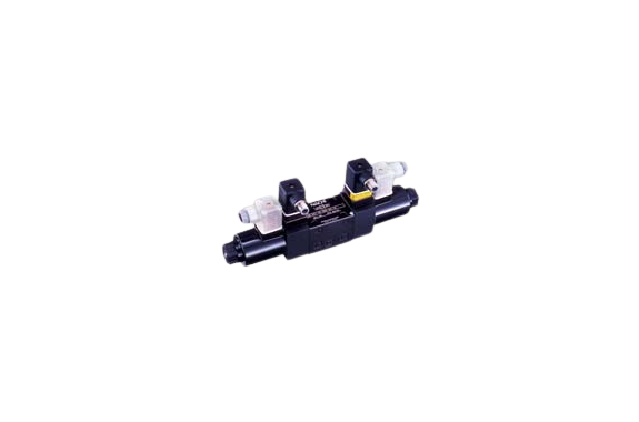
Made in: Japan
Manufacturer: NACHI
Model: SAW-G01
Features
It is a solenoid valve that monitors the direction switch position of the valve and possesses the function of outputting a signal.
It operates the switch directly with the valve operation so reliable output can be obtained.
It does not use magnetic sensors or proximity sensors so the temperature drift and hysteresis are smaller than before.
Specifications
| Series | SAW-G01 | |
| Type | Spool type | |
| Max, working pressure | Standard type | 35MPa |
| Shock-less type | 25MPa | |
| Max.flow | Standard type | 30 to 100 L/min (Note 1) |
| Shock-less type | 30, 50 L/min (Note 1) | |
| Switch specifications | rated voltages DC24V Maximum load current: 100mA Residual voltage: max 1.2V | |
(Note 1) The maximum flow differs depending on the valve format and working pressure.
Working principle
When the spool is in a neutral state, the fixed points of contact and the moving points of contact touch and are in a state of electrical conductance. When the spool begins to operate, the moving points of contact move to the left side in tandem with it, and the fixed points of contact and moving points of contact enter a state of electrical non-conductance.
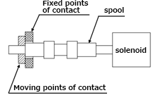
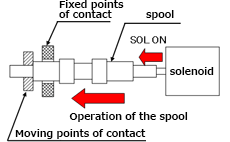
Spool neutral state (SOL OFF) Spool operating state (SOL ON)
Pressure – permissible flow value
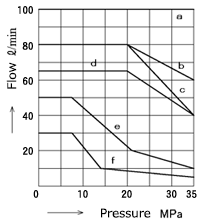
| Operation symbol | JIS symbol | Standard AC, DC solenoid attachment | ||
|---|---|---|---|---|
| A2X | – | f | f | |
| A3X | b | f | f | |
| A5 | a | – | e | |
| C1 | AC SOL. d DC SOL. c | e | e | |
| C5 | a | e | e | |
| C6 | AC SOL. d DC SOL. c | e | e | |
| C1S | a | e | e | |
| C6S | a | e | e | |
Valve pressure loss
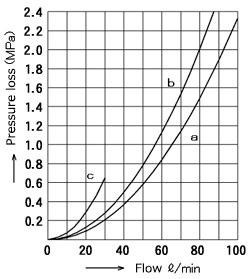
| Operation symbol | JIS symbol | P → A | P → B | A → T | B → T |
|---|---|---|---|---|---|
| A2X | c | c | – | – | |
| A3X | b | b | b | b | |
| A5 | – | b | b | – | |
| C1 | b | b | a | b | |
| C5 | b | b | b | b | |
| C6 | b | b | a | a | |
| C1S | b | b | b | b | |
| C6S | b | b | b | b |
Application
- You can use this valve when designing and manufacturing mechanical equipment that complies with the standard for safety of machinery (ISO 12100) and the JIS standard (JIS B 9700).
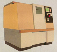
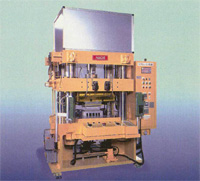
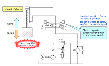
Example of the use of an electromagnetic switching valve with a monitoring switch
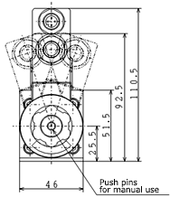
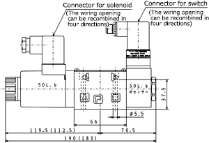
Mounting dimensions
The installation dimensions of the gasket surface are ISO 4401-03-02.

Related Products
-
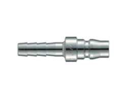
NAC- AL TYPE 20 Steel (Chrome-plated) PH (Hose nipple)
-
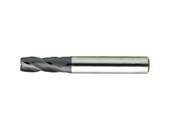
SAKUSAKU EHB412060 Square End Mill 4-Flute
-
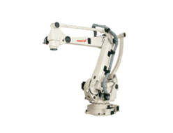
Nachi LP130F Palletizing Robots
-

Eagle Clamp UGHA Type Clamp for U-shaped Groove / Groove Lid / Clamp for Curb
-
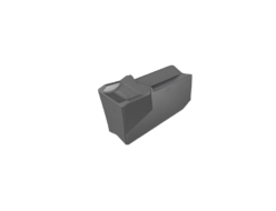
SAKUSAKU DIMC4 6R Insert For Grooving / Parting Off With C-type Chip Breaker
-
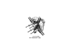
Miyakawa S-204 Multi-axis attachment S type


