Nikki Co., Ltd.
Nikki Bare Crimp Terminal
Manufacturer: Nikki Co., Ltd.
What are crimp terminals?
Crimp terminals are necessary components for connecting electrical wires to electrical devices and transmitting electricity and signals.
Developed around 1925, before crimp terminals became widespread, soldering was the mainstream method of connection.
Benefits of using crimp terminals
In addition to using crimp terminals, other methods of connecting electrical wires to electrical devices include soldering or securing the connections with insulating tape.
However, connecting by soldering requires skill and there is a risk of burns.
In addition, if you use insulating tape to secure the wires, there is a risk of short circuits, and it is difficult to neatly bundle together electrical wires of different thicknesses, types, and standards.
With crimp terminals, you don’t have to worry about getting burned or connecting different electrical wires!
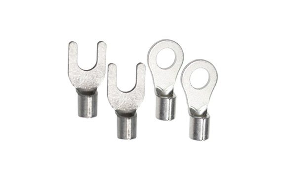
Bare crimp terminals offered by our company
We offer two types of terminals: bare crimp terminals (round/R type) and bare crimp terminals (open tip/Y type).
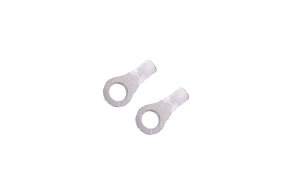
Bare crimp terminal (round type/R type)
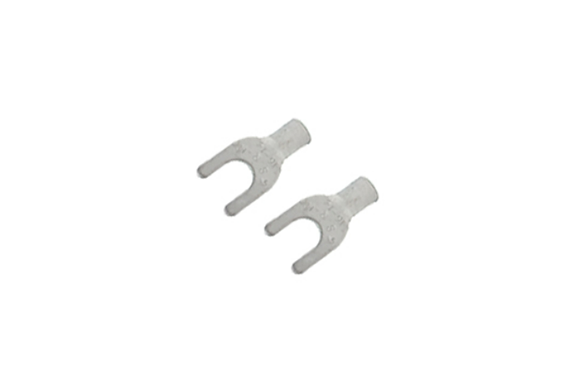
Bare crimp terminal (open end/Y type)
When using it, it doesn’t actually matter which crimp terminal you choose.
Here we will introduce some selection points to help you choose the right crimp terminals more smoothly.
Selection points
- 1. “Round type/R-type” and “Open end type/Y-type”
- The advantage of the “round/R type” is its safety.
- On the other hand, the advantage of the “leading edge type/Y type” is that it is easy to work with.
- Therefore, the key point in making a selection is whether to prioritize safety or ease of use.
| Advantages | ×Disadvantages | |
|---|---|---|
| Round/R type | It is a little cheaper than the tip-opening type, which is safer . Even if the screw loosens a little, it will still be attached. *Loosening to the point where the terminal floats may cause a spark. | Poor workability (e.g., screws must be completely removed before installation) |
| Open end type/Y type | Easy to use (e.g. no need to remove screws, can be installed immediately) | Less safe. Compared to the round type, it is a little more expensive. Ex. If the screw becomes loose, it will come off. Ex. There is a risk of direct contact with electricity. |
- 2. Advantages and disadvantages of “bare crimp terminals”
- The advantage of “bare” is that it reduces work time and is cheaper than insulation.
- However, if installed in an exposed location, there is a risk of direct contact with electricity, so you will need to insulate it with heat shrink tubing after installation, which requires extra work.
| Advantages | ×Disadvantages | |
|---|---|---|
| naked | Compared to insulation, which can shorten the work time , it is cheaper . For example, attach it to a place that cannot be touched directly, such as a lid. | Depending on the installation location, it may be necessary to insulate it later. |
It is often said that the choice of crimp terminals ultimately comes down to personal preference.
It seems that the more experienced the technician is, the more intuitive and intuitive they are at using the system.
However, when you are still inexperienced, you may not know what criteria to use.
If you have any questions or concerns about crimp terminals, please feel free to contact us.
Specification
| Material | Oxygen-free copper |
|---|---|
| Quantity | 100 pieces |
Y-type main dimensions
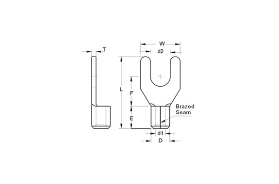
| Model | Nominal cross-sectional area ( mm2 ) | Stud diameter | Dimensions of each part (mm) | Conjugation range of fit | ||||||||
|---|---|---|---|---|---|---|---|---|---|---|---|---|
| ød2 | W | F | L | E | øD | ød1 | T | Stranded wire mm2 | AWG | |||
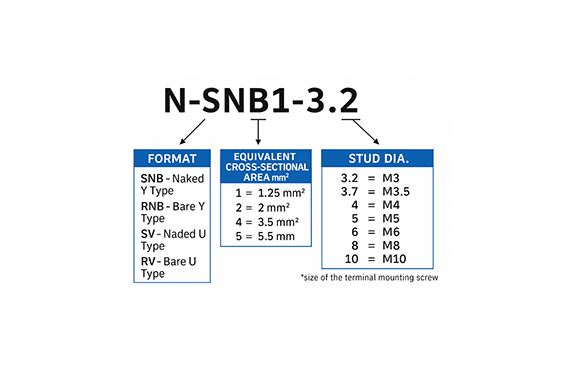
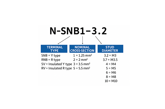
| N-SNB1-3.2 | 1.25 | M3 | 3.2 | 5.7 | 6.5 | 16.0 | 4.8 | 3.4 | 1.7 | 0.75 | 0.5-1.5 | 22-16 |
| N-SNBS1-3.7 | M3.5 | 3.7 | 5.7 | |||||||||
| N-SNBL1-3.7 | 3.7 | 6.4 | ||||||||||
| N-SNBS1-4 | M4 | 4.3 | 6.4 | |||||||||
| N-SNBM1-4 | 4.3 | 7.2 | ||||||||||
| N-SNBL1-4 | 4.3 | 8.1 | ||||||||||
| Model | Nominal cross-sectional area ( mm2 ) | Stud diameter | Dimensions of each part (mm) | Conjugation range of fit | ||||||||
|---|---|---|---|---|---|---|---|---|---|---|---|---|
| ød2 | W | F | L | E | øD | ød1 | T | Stranded wire mm2 | AWG | |||
| N-SNB2-3.2 | 2 | M3 | 3.2 | 5.7 | 6.5 | 16.0 | 4.8 | 4.1 | 2.3 | 0.80 | 1.5-2.5 | 16-14 |
| N-SNBS2-3.7 | M3.5 | 3.7 | 5.7 | |||||||||
| N-SNBL2-3.7 | 3.7 | 6.4 | ||||||||||
| N-SNBS2-4 | M4 | 4.3 | 6.4 | |||||||||
| N-SNBM2-4 | 4.3 | 6.4 | ||||||||||
| N-SNBL2-4 | 4.3 | 8.1 | ||||||||||
| N-SNBS2-5 | M5 | 5.3 | 8.1 | |||||||||
R type main dimensions
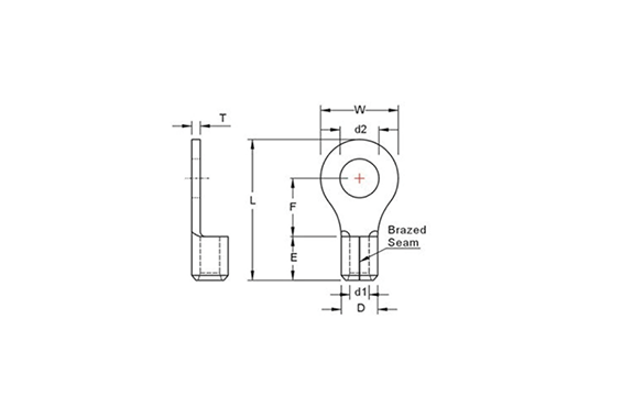
| Model | Nominal cross-sectional area ( mm2 ) | Stud diameter | Dimensions of each part (mm) | Conjugation range of fit | ||||||||
|---|---|---|---|---|---|---|---|---|---|---|---|---|
| ød2 | W | F | L | E | øD | ød1 | T | Stranded wire mm2 | AWG | |||
| N-RNB1-3.2 | 1.25 | M3 | 3.2 | 5.5 | 5.0 | 12.5 | 4.8 | 3.4 | 1.7 | 0.75 | 0.5-1.5 | 22-16 |
| N-RNBS1-3.7 | M3.5 | 3.7 | 5.5 | 5.0 | 12.5 | |||||||
| N-RNBM1-3.7 | 3.7 | 6.6 | 6.3 | 14.4 | ||||||||
| N-RNBS1-4 | M4 | 4.3 | 6.6 | 6.3 | 14.4 | |||||||
| N-RNBL1-4 | 4.3 | 8.0 | 7.0 | 15.8 | ||||||||
| N-RNB1-5 | M5 | 5.3 | 8.0 | 7.0 | 15.8 | |||||||
| N-RNB1-6 | M6 | 6.4 | 11.6 | 11.0 | 21.8 | |||||||
| N-RNB1-8 | M8 | 8.4 | 11.6 | 11.0 | 21.8 | |||||||
| N-RNB2-3.2 | 2 | M3 | 3.2 | 6.6 | 4.8 | 12.8 | 4.1 | 2.3 | 0.80 | 1.5-2.5 | 16-14 | |
| N-RNBM2-3.7 | M3.5 | 3.7 | 6.6 | 6.3 | 14.4 | |||||||
| N-RNBS2-4 | M4 | 4.3 | 6.6 | 6.3 | 14.4 | |||||||
| N-RNBL2-4 | 4.3 | 8.5 | 7.4 | 16.5 | ||||||||
| N-RNBS2-5 | M5 | 5.3 | 8.5 | 7.4 | 16.5 | |||||||
| N-RNBL2-5 | 5.3 | 9.5 | 7.4 | 17.0 | ||||||||
| N-RNB2-6 | M6 | 6.4 | 12.0 | 11.0 | 21.8 | |||||||
| N-RNB2-8 | M8 | 8.4 | 12.0 | 11.0 | 21.8 | |||||||
| Model | Nominal cross-sectional area ( mm2 ) | Stud diameter | Dimensions of each part (mm) | Conjugation range of fit | ||||||||
|---|---|---|---|---|---|---|---|---|---|---|---|---|
| ød2 | W | F | L | E | øD | ød1 | T | Stranded wire mm2 | AWG | |||
| N-RNB3-4 | 3.5 | M4 | 4.3 | 8.0 | 8.0 | 18.0 | 6.0 | 5.1 | 2.9 | 1.0 | 2.5-4 | 14-12 |
| N-RNBM3-5 | M5 | 5.3 | 9.5 | 9.2 | 20.0 | |||||||
| N-RNB3-6 | M6 | 6.4 | 12.0 | 9.4 | 21.4 | |||||||
| N-RNB3-8 | M8 | 8.4 | 15.0 | 13.3 | 27.0 | |||||||
| N-RNBS5-4 | 5.5 | M4 | 4.3 | 7.2 | 6.1 | 15.7 | 5.6 | 3.4 | 4-6 | 12-10 | ||
| N-RNBL5-4 | 4.3 | 9.5 | 8.3 | 19.0 | ||||||||
| N-RNB5-5 | M5 | 5.3 | 9.5 | 8.3 | 19.0 | |||||||
| N-RNB5-6 | M6 | 6.4 | 12.0 | 10.5 | 22.5 | |||||||
| N-RNB5-8 | M8 | 8.4 | 15.0 | 13.3 | 27.0 | |||||||
| N-RNB5-10 | M10 | 10.5 | 15.0 | 13.3 | 27.0 | |||||||
Related Products
REQUEST QUOTATION

PAYMENT

LINK


