Nippon Gear Co.
Nippon Gear JMB Series
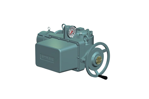
Manufacturer: Nippon Gear Co., Ltd.
Model: JMB Series
Features
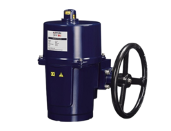
Electric/manual mode switching operation
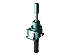
- In the case of JMB-00 and larger sizes, pulling the hand wheel switches to manual mode and pushing it switches to electric mode.
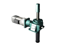
- JMB-04 and 03 are equipped with the declutch lever. Operating the lever switches between manual mode and electric mode.
- The interlock switch is provided as standard. In manual mode, the control to disable electric operation is implemented to prevent accidents.
High-precision geared limit switch
- operating point can be set at any position within the entire stroke.
- The limit switch is operated by the intermittent gear without fail. The preset position does not shift.
- Various contact types ranging from 2-line 8-contact to 4-line 16-contact (option) can be selected according to the application.
Enhanced control functions
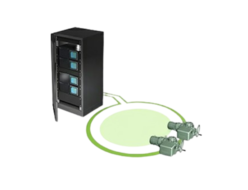
- Integral control, consisting of various control devices, is applicable to the control station (control panel) and computerized control.
- It enables development into a centralized system that networks multiple actuators.
High-performance torque switch
- The operating point of the torque switch can be set to any value. It protects the valve and drive mechanism from overloads in both the opening and closing directions without fail.
- The rotary type equipped with the 1a and 1b contacts in both the opening and closing directions, open type equipped with the 1b contact, and microswitch type equipped with the 1c contact are available.
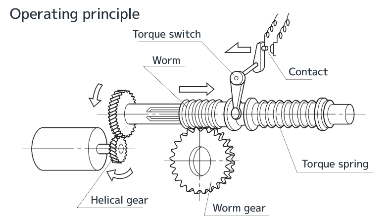
1. The driving force of the motor rotates the worm gear through the helical gear and worm.
2. A stem nut engaged with the valve stem screw is fixed inside the worm gear, and the rotation of the stem nut moves the valve stem up and down to open and close the valve.
3. The worm moves while compressing the torque spring in proportion to an increase in the torque of the worm gear, and simultaneously rotates the torque switch.
4. If the torque of the worm gear reaches a preset value, the contact of the torque switch opens to stop the motor.
Highly-durable gear train
- Worm gears and worms are made of aluminum bronze and carbon steel or chrome molybdenum steel, respectively. They can withstand high output and loads and maintain superior performance over a long period of time.
- Optimum materials are used for the respective gears according to the loads, and extreme pressure grease is filled in the sealed gear case.
- Ball bearing is used. A taper roller bearing is used for the output shaft that receives thrusts to realize stability-oriented design.
Equipped with the earth terminal/space heater as standard
- All models are equipped with an earth terminal and a space heater as standard. They can be used in a wide variety of fields.
Easy maintenance
- The stem nut has dual (two-piece) structure. The drive sleeve and stem nut are detachable because they are engaged with a spline.
- When replacing the stem nut, the actuator and electric wire do not need to be removed.
- Because the motor and worm gear have independent structures, the self-locking feature of the worm gear prevents the valve from operating under its own weight even with the motor dismounted. And the valve can be opened and closed manually even in this state (in the case of standard gear ratio).
Specifications
| Unit size | JMB-04 | JMB-03 | JMB-00 | JMB-0 | JMB-1 | JMB-2 | JMB-3 | JMB-4 | |||
|---|---|---|---|---|---|---|---|---|---|---|---|
| Mechanism and specifications | Allowable torque N・m | 110 | 250 | 360 | 1000 | 1500 | 2700 | 6100 | 11500 | ||
| Allowable thrust kN | 35 | 49 | 62 | 105 | 200 | 320 | 620 | 1100 | |||
| Minimum and maximum stem diameter*1 (mm) | Exterior thread | 2PC | 26以下 | 38以下 | 20-46 | 24-60 | 38-73 | 42-86 | 55-127 | 60-127 | |
| 1PC | ー | 45-51 | 60-70 | 73-83 | 86-98 | 127-146 | 127-171 | ||||
| Interior thread | 2PC Maximum keyway | 20以下 6×2.8 | 32以下 10×3.3 | 20-36 10×3.3 | 25-47 14×3.8 | 30-60 18×4.4 | 35-70 20×4.9 | 35-100 28×6.4 | 45-110 28×6.4 | ||
| 1PC Maximum keyway | 25以下 8×3.3 | 38以下 10×3.3 | 25-44 12×3.3 | 35-58 16×4.3 | 45-67 20×4.9 | 50-80 22×5.4 | 70-120 32×7.4 | 90-152 40×9.4 | |||
| Output shaft rotation frequency(min-1)*2 (Standard reduction rate of electric type) | 60Hz | 15.1-48.3 | 15.4-49.4 | 14.7-69.5 | 16.2-59.0 | 18.1-58.8 | 19.4-68.6 | 15.4-44.6 | 12.8-30.9 | ||
| 50Hz | 12.7-40.8 | 13.0-41.7 | 12.4-58.6 | 13.7-49.7 | 15.3-49.6 | 16.4-57.8 | 13.0-37.6 | 10.8-26.1 | |||
| Reduction rate of manual type | JMB model (standard) | ー | 45 | 38 | 34 | 33 | <41/td> | 49 | |||
| JMB-H model (equipped with HWA)*3 | ー | 38×3.2 | 34×3.6 | 33×3.9 | 41×5.5 | 49×6.75 | |||||
| Attachable motor(kW) | 0.2 0.4 | 0.2 0.4 | 0.4 0.75 1.5 | 0.75 1.5 2.2 | 1.5 2.2 3.7 | 3.7 5.5 | 5.5 7.5 11.0 15.0 | 11.0 15.0 18.5 22.0 | |||
| Attachable actuator | BA (Allowable thrust: 26 – 1,200 kN, for multi-turn-type valve) HB(Allowable torque: 0.83 – 200 kN·m, for part-turn-type valve) H (Allowable torque: 390 – 1,100 kN·m, for part-turn-type valve) | ||||||||||
| Electric and control specifications | Torque switch | JMB-04, 03: 1c in both opening and closing directions (microswitch type) JMB-00 to 4: 1a and 1b in both opening and closing directions (Rotary type) | |||||||||
| Geared limit switch | JMB-04, 03: 2 contacts (1a, 1b) x 2 lines (standard) JMB-00 to 4: 4 contacts (2a, 2b) x 2 lines (standard) | ||||||||||
| Motor | Power supply | 200 V AC class, 400 V AC class/50Hz, 60Hz 100 V DC class, 200 V DC class | |||||||||
| Insulation class | Class E (standard), class B, and class H (option) | ||||||||||
| Rated time | 30 minutes or 15 minutes (standard) | ||||||||||
| Space heater | Option | ||||||||||
| Indication light | Option | ||||||||||
| Push-button switch | |||||||||||
| Position transmitter | |||||||||||
| Electromagnetic switch | |||||||||||
| Proportional braking system | |||||||||||
| Others | |||||||||||
| Protection type | Protection structure | Standard(IP55) | |||||||||
*1 2PC: The stem nut is detachable. High in maintainability and recommended for exterior thread-type valves
1PC: The stem nut and sleeve are integrated.
*2 An estimate based on the rated rotation frequency of the motor (60 Hz: 1,600 rpm, 50 Hz: 1,350 rpm)
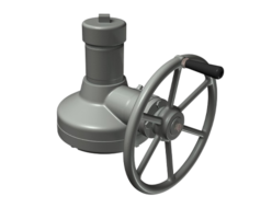
*3 A JMB model actuator equipped with a manual reducer (hand wheel attachment called “HWA”) is called the JMB-H model.
The manual reducer is used when the standard manual operating force is insufficient.
Reduction ratio represents the standard reduction ratio x HWA reduction ratio.
REQUEST QUOTATION

PAYMENT

LINK


