NOHMI BOSAI
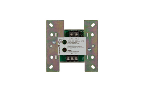
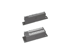
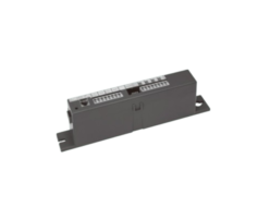
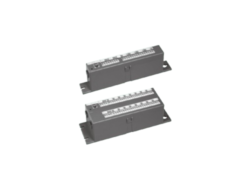
NOHMI BOSAI FRRU004-MOM4 Monitored Output Module
Manufacturer: NOHMI BOSAI
Model: FRRU004-MOM4
Features of FRRU004-MOM4
- Simple LED for status indication.
- Supports NFPA Class A (Styles 6 & 7) and Class B (Style 4) for SLC.
- Supports NFPA Class B (Style Y) for NAC.
- UL listed with Potter/Amseco®, Gentex®, and Cooper Wheelock® syncro-modules and devices.
- Electronic address setting for ease of configuration.
- Compact design for efficient installation.
- Easy and quick to install.
Description
- The FRRU004-MOM4 Monitored Output Module provides a programmable power source to control output devices like notification appliances and releasing devices. It continuously monitors wiring connected to terminals A+, A- for open or short circuits, along with 24+ and 24- when 24VDC is applied.Additionally, the module includes a red LED to indicate status. In normal conditions, the LED flashes. Once activated, the LED stays lit. If a problem occurs, the LED will turn off, allowing for quick troubleshooting.
Specifications of FRRU004-MOM4
| No. | Item | Specification |
|---|---|---|
| 1 | Rated voltage range of SLC input power (S+,S-) | 22.0 to 24.0V |
| 2 | Maximum SLC 24 VDC standby current (S+,S-) | 250µA |
| 3 | Maximum SLC 24 VDC alarm current (S+,S-) | 1mA |
| 4 | Rating for connected device power (Releasing device and NAC) | 24VDC, 2A |
| 5 | Max. supervising current for external 24 VDC input power (24+,24-) | 1.6mA |
| 6 | Wiring style | NFPA Class B (Style Y) |
| 7 | End-of-line resistor value for notification appliance | 5.1kΩ, 1/2W |
| 8 | End-of-line device for releasing device | 5.1kΩ, 1/2W with diode |
| 9 | Maximum wiring resistance of output circuit wiring | Refer to Wiring diagram |
| 10 | Maximum wiring capacitance of output circuit wiring | 1µF |
| 11 | Operating temperature range | 0°C to 49°C (32°F to 120°F) |
| 12 | Operating humidity range | 0 to 93% (non-condensing) |
| 13 | Dimensions | 106mm (4.17 inches) (H) × 106mm(4.17 inches) (W) × 29mm (1.14 inch) (D) |
| 14 | Applicable electrical box for installation | North American 64mm (2-1/2 inches) deep 2-gang box; Standard 4 inches square box 38mm (1-1/2 inch) deep box |
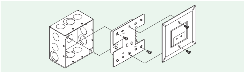
Installation
Figure 1: Installation into the compatible electrical box
Wiring Diagram
Figure 2: Output Connected to a NAC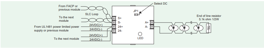
Figure 3: Output Connected to a Releasing Device 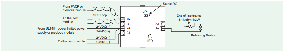
Related Products
-
NOHMI BOSAI NN83CU Storage Cylinder
-
NOHMI BOSAI FRRJ001A-Y-SS/FRRJ001-Y-2SS/FRRJ001-Y-4SD Addressable Module, Dry Contact Type
-
NOHMI BOSAI FRRJ001A-Y-G Addressable Module For Gas Detector
-

NOHMI BOSAI FDPJ Series Rate-Of-Rise Heat Detector
-
NOHMI BOSAI FRRJ001A-Y-S/FRRJ001-Y-4S Addressable Module, Wet Output Type
-
NOHMI BOSAI CSC004 System Interface Unit (SIU)
REQUEST QUOTATION

PAYMENT

LINK


