NOHMI BOSAI
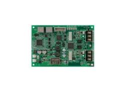
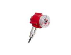
NOHMI BOSAI FRRU004-SCM4 Single Contact Module
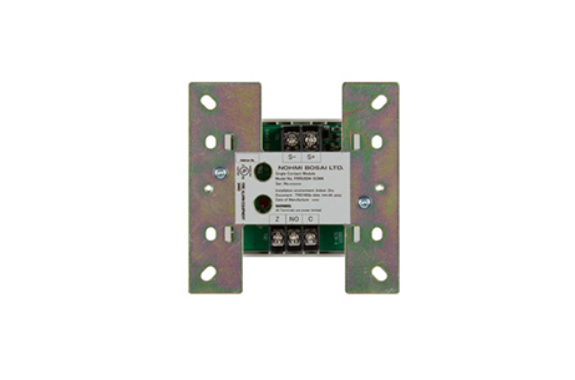
Manufacturer: NOHMI BOSAI
Model: FRRU004-SCM4
Features of FRRU004-SCM4
- One simple LED for status indication
- NFPA Class A (Styles 6 & 7) and Class B (Style 4) for SLC
- NFPA Class A (Style D) and Class B (Style B) for IDC
- Electronic address setting
- Downsized unit
- Easy installation
Description
- The Conventional Initiating Zone Module (FRRU004-CIZM4) supervises conventional initiating devices connected to an Initiating Device Circuit (IDC). This module detects an alarm and sends a report to the Fire Alarm Control Panel (FACP). It also monitors the wiring (A+, A-, B+, B- wires) and power supply to detect open circuits.In addition, the module works with IDC wiring styles compliant with NFPA Class B (Style B) and Class A (Style D). When the module detects an alarm, it locks the status until the system resets. If used in Class A (Style D) wiring, the module also latches if it detects open circuits.
Moreover, the FRRU004-CIZM4 has a red LED that indicates the status of the module and its wiring. In normal conditions, the LED flashes, while a constant light signals an alarm. An open circuit is shown by the LED turning off.
Specifications of FRRU004-SCM4
| No. | Item | Specification |
|---|---|---|
| 1 | Rated voltage range of SLC input power (S+,S-) | 22.0 to 24.0V |
| 2 | Maximum SLC 24 VDC standby current (S+,S-) | 250μA |
| 3 | Maximum SLC 24 VDC alarm current (S+,S-) | 1mA |
| 4 | IDC input circuit wiring style | Class B (Style B) |
| 5 | End-of-line resistor for IDC | 5.1kΩ, 1/2W |
| 6 | Maximum wiring resistance of IDC | 100Ω |
| 7 | Maximum wiring capacitance of IDC | 1μF |
| 8 | Operating temperature range | 0°C to 49°C (32°F to 120°F) |
| 9 | Operating humidity range | 0 to 93% (non-condensing) |
| 10 | Dimensions | 106mm (4.17 inches) (H) x 106mm (4.17 inches) (W) x 29mm (1.14 inch) (D) |
| 11 | Applicable electrical box for installation | North American 64mm (2-1/2 inches) deep 2-gang box, Standard 4 inches square box 38mm (1-1/2 inch) deep box |
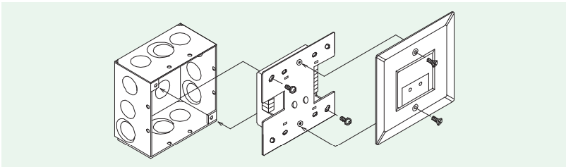
Installation
Figure 1: Installation into the compatible electrical box
Wiring Diagram
Figure 2: Wiring diagram in case of supervising Normally-open contact
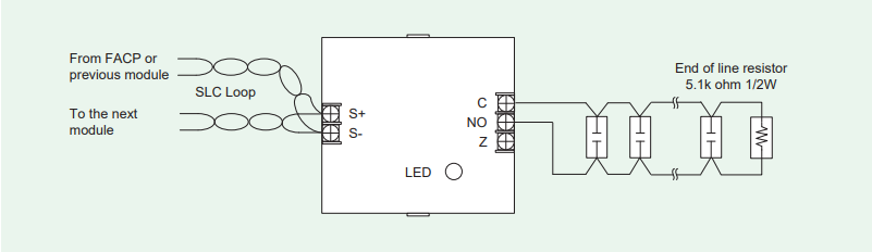
Figure 3: Wiring diagram in case of supervising Normally-closed contact (Not recognized as NFPA Initiating Device Circuit) 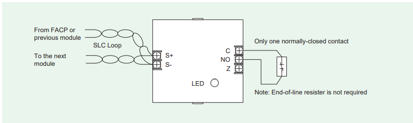
Related Products
-
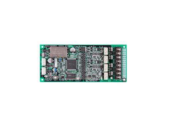
NOHMI BOSAI PCA-2706XA-NIU Network Interface Unit
-
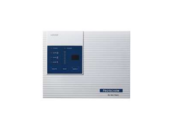
NOHMI BOSAI FDNA002-R Protecview Aspirating Super-High Sensitivity Smoke Detection System
-
NOHMI BOSAI PCA-N3060-SCU Sub Control Unit
-
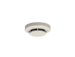
NOHMI BOSAI FDKU634-D-X Multi-criteria Conventional Smoke Detetor
-
NOHMI BOSAI PDCJ002-E Infrared Three-Wavelength Flame Detector
-
NOHMI BOSAI FZBU005-AIB Addressable Isolator Base
REQUEST QUOTATION

PAYMENT

LINK


