Japan, Orientalmotor
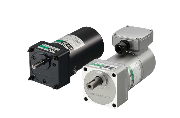
Orientalmotor Electromagnetic Brake Motors
Made in Japan
Manufacturer: ORIENTAL MOTOR CO., LTD.
Product name: Electromagnetic Brake Motors
Electromagnetic Brake Motor Features
Equipped With Power Off Activated Type Electromagnetic Brake
This is a mechanical brake motor with a power off activated type electromagnetic brake. The motor shaft can be stopped as soon as the power is turned OFF, such as during a power failure.
Ideal for applications that require load holding, such as vertical operation.
Brake Pack to Provide Instantaneous Stop of the Motor
Suitable for applications to reduce the overrun and provide instantaneous stop of electromagnetic brake motors. The brake pack SB50W is equipped with a function that can output an alarm signal when the thermal protector built into the motor is activated.

Conforms to International Safety Standards
All models conform to various safety standards and have built-in overheat protective devices.
Applicable Standards
UL/CSA Standards Certified
Component certified under the China Compulsory Certification System (CCC System)
Implemented CE Marking (Low Voltage Directive)
Motor Overheat Protective Device
Thermal Protector,
Impedance Protected Motors


Three-Phase High Efficiency Motors With Optimized Design are Also Available
A review of the basic motor design has yielded unprecedented high efficiency and energy savings.
Also available are three-phase high efficiency motors with characteristics best suited for speed control by inverters, enabling energy saving.
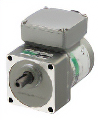
KIIS Series
Maximum Efficiency of 80 %
Specialized components and an optimal magnetic design are used to make high efficiency three-phase motors with a max. efficiency of 80 %. Motors are fanless with increased motor output power, and significant loss reduction.
Comparison of Max. Efficiency (Reference values)

[Rated Output Power at 60 Hz]
*Three-Phase 380/400/415 VAC meets IE3 reference values.
IE4 and IE3 are efficiency classes under the international standard IEC 60034-30-1.
Power Consumption Reduced by up to 10 %
Compared to a conventional 90 W motor under the same conditions, power consumption is reduced by a maximum of about 10 %. This helps the equipment to save energy.

Increased Motor Output Power
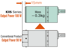
Output power of 100 W in a 90 mm frame size is achieved through increased efficiency. An overall length 15 mm shorter than the conventional motor contributes to equipment downsizing
Fanless
With reduced loss, there is less heat generation in the motor. Because of this, the cooling fan that was incorporated into the conventional 60 W min. products is no longer included.

No Dust, etc.
With no cooling fan, dust is not blown around.
Features of Gearheads and Linear Heads
Gearheads: Easy Deceleration and Torque Increase
By combining the motor and gearhead, it is possible to reduce the speed to the desired speed or increase the torque.

LJ Linear Heads: Converts Motor Rotation to Linear Motion
Combined with a linear head, the rotary motion of the motor can be converted to linear motion. Square rack type and round rack type are available.

Wide Variation
Different gearheads can be used for different applications.

High-Strength Gearhead
For increased torque or downsizing, we offer high-strength gears with even more power.
Parallel Shaft GV Gearhead
Increased torque is achieved by increasing the size of the output shaft bearing and adopting carburized gears.

Optimal for Inverter Drive Three-Phase High Efficiency Motors
Can be Combined With Other Manufacturers’ Inverters
The three-phase high efficiency motor KIIS Series can be used in combination with inverters made by other manufacturers used by the customer. Easily control speed by combining with your existing inverter.

KIIS Series
Example of Characteristics When Combining KIIS Series 100 W Round Shaft Type and Mitsubishi Electric Inverter E800

Combination Characteristics Data for Inverters and Optimal Parameters are Available.
The best torque characteristics can be obtained by setting the inverter parameter values to match the motor.
For combination characteristics data and parameter setting examples of KIIS Series and other manufacturers’ inverters, refer to the links below.
Combining the KIIS Series With an Inverter Contributes to Improved Equipment Performance.
Wide Range of Speeds
Using an inverter, a wide speed range can be controlled, from 3 Hz to a maximum of 120 Hz (90~3600 r/min)*. Designed for use at high rotation speeds, including the gearhead.
*Speed control range differs depending on the product. Refer to “Other Specifications” – “Using with Inverters” on each product detail page.

Vector Control Improves Torque in the Low to Medium Speed Range
By using vector control as the control method for the inverter, high torque can be achieved from low speed.

Improved Speed Stability
When combined with an inverter, the speed decrease is reduced even when the load fluctuates, allowing for stable speed control.

Supports High-Speed Rotation
Creep-free bearings, etc. are used in the round shaft type, and components capable of handling high-speed rotation have been selected and designed for inverter control.

Reinforced Insulation for Use in Areas With High Power Supply Voltage (200 W output power)
Three-Phase 380/400/415 VAC input motor (200 W output power only) has reinforced insulation against micro-surge voltages generated when driving inverters and can be used safely in combination with inverters.
Note: Electronic thermal function of the inverter or an electromagnetic switch must be used.
The motor has no built-in overheat protective device (thermal protector).
An electronic thermal function of the inverter or an electromagnetic switch must be used to prevent burnout of the motor if the motor output shaft is constrained for any reason.
- For examples of the electronic thermal settings when combining an inverter made by another manufacturer with the KIIS Series, refer to the combination characteristics data.
- For recommended electromagnetic switches, refer to “Other Specifications” on the product details page.
Electromagnetic Brake Structure and Brake Operating Characteristics
Principle of Operation of Power Off Activated Type Electromagnetic Brake
The electromagnetic brake motor is equipped with a power off activated type electromagnetic brake for braking. An example of the structure is shown in the figure on the right. When voltage is applied to the exciting coil (①), the armature (③) is attracted to the electromagnet in resistance to the coil spring (②) and the brake is released, allowing the motor shaft to rotate freely. When no voltage is applied, the armature (③) is released and the coil spring (②) causes the brake lining (⑤) to press against the brake hub (④), holding the motor shaft in place.

Electromagnetic Brake Control Characteristics
This chart shows the relationship between the inertia and braking characteristics of the electromagnetic brake motor (braking time and overrun). Braking time and overrun represent the time and overspeed (overrun) from the moment the power is turned off until the motor stops. In the case of 25 W, when operating with an inertia converted to the motor shaft of 0.3 [×10-4kgm2], the braking time will be 140 msec and the overrun will be 2.4 revolutions.

Motor Performance Comparison
Rotation Speed and Speed Control Range
Standard AC motors (constant speed motors) such as induction motors, vary their rotation speed according to the power supply frequency, and the rated speed is approximately 1200 r/min at a frequency of 50 Hz and approximately 1450 r/min at 60 Hz. Speed control motors are available for a wide range of operating speeds from low to high.

Stopping Accuracy
When the motor is stopped, an overrun (overshoot) occurs.
Overruns can be reduced when the electromagnetic brake motor or instantaneous stop function are used.

Applications
Load Retention at Stop
The Motor Stops Instantly When the Power is Turned OFF
Inclined Conveyor
Conveyor: Instantaneous Stop
Simple Positioning and Less Overrun When Combined With a Brake Pack
Electromagnetic Brake Can be Controlled by Brake Pack


