Osaka Blower MFG. CO., LTD.
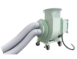
Osaka Blower Turbo Fans

Manufacturer: Osaka Blower
Product Type: Turbo Fans
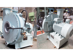
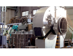
Structure
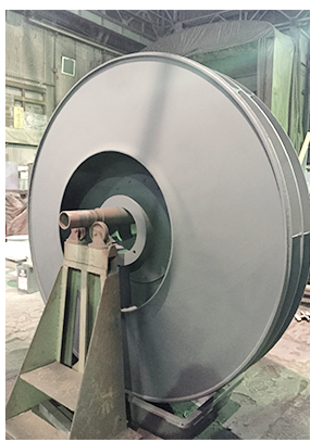
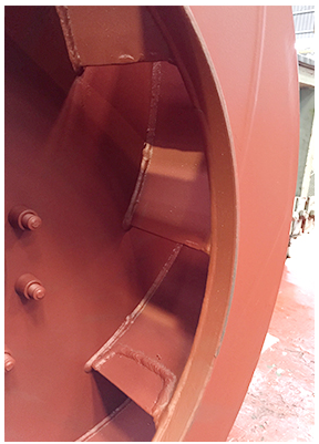
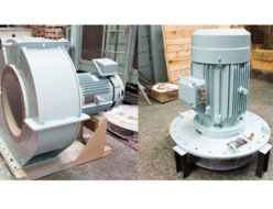
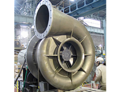
The impeller consists of 10 to 20 small backward-curved blades made of stainless steel or cast iron, designed to withstand high-speed operation. These blades are either riveted onto the main disk or firmly assembled using a circular wedge-shaped side plate with rivets or welding. This structure is tested for dynamic balance to eliminate misalignment and prevent vibration.
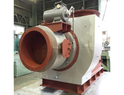
The casing is primarily made of thick plate material to ensure high strength under mechanical and external conditions. Reinforcement ribs are added as needed to further enhance strength, reduce vibration, and minimize external deformation.
Bearings generally use ball or roller bearings, selected for long service life. Depending on conditions, sleeve bearings may also be used.
For lubrication, grease is commonly used, but depending on the operating conditions, oil lubrication, forced lubrication, or water cooling may be applied. The cooling methods include natural air cooling, forced air cooling, and water cooling.
All design decisions regarding fan application and operational conditions are based on our company’s past experience and track record.
Features and Applications
Turbo fans are suitable for relatively high-pressure applications in the range of 0.25 to 10 kPa. Their applications include:
- Forced draft fans for boilers
- Induced draft fans
- Secondary air fans
- Ventilation fans
- Heating and cooling fans
- Dust collection fans
- Gas compression fans
- Air supply fans
Due to their versatility, turbo fans are widely used across various industries today.
One of the key features of this fan is its high efficiency among centrifugal fans, low noise levels, and large airflow capacity. Unlike multi-stage blowers, turbo fans do not have significant limitations on discharge airflow. Additionally, when combined with inlet vane control systems, these fans can efficiently adjust performance under partial loads without major losses.
Furthermore, the change in airflow is minimal, making it ideal for series operation. Compared to other centrifugal fans, turbo fans require less additional power when increasing airflow, making them energy-efficient.
Inlet Vane Control
Inlet Vane Control is a method of controlling airflow by installing adjustable guide vanes at the intake of a fan. These vanes are mechanically linked, as shown in the image, and can open and close to create a swirling airflow in the same direction as the impeller rotation. This reduces the pressure rise and input power of the fan, effectively controlling the airflow.
The pressure rise and power input of the fan are proportional to (U₂C₂ – U₁C₁), as shown in Figure 7 (velocity triangle diagram). By imparting a swirl in the same direction as the impeller rotation, the C₁u component increases, thereby reducing the energy required to move the air. When the swirl direction is adjusted with vane openings, the pressure rise and power input can be efficiently controlled.
Advantages Compared to Other Control Methods
Figure 8 illustrates the advantages of inlet vane control compared to other control methods. The key benefits include:
- Wider control range compared to damper control
- Higher efficiency than speed control in certain ranges (10% to 70% of rated flow)
- Energy savings when combined with other control systems
- Compact and simple mechanism
- Reduced noise and vibration
Since inlet vane control mechanisms can be operated manually or automatically, they allow for seamless integration with automation systems, providing immediate operational effects.
Application Example in Boiler Draft Fans
Figure 9 shows an example of an inlet vane control system used in boiler draft fans. The mechanism employs a unique spherical-link system, which ensures smooth movement and minimal wear. For high-load applications, oil-free metal bearings are used to reduce friction and enhance durability.
In cases where high-temperature airflow, corrosive gases, or heavy dust loads are present, the external movement type mechanism is used to prevent damage.
Inlet Vane Control
Inlet Vane Control is a method of airflow regulation that involves the installation of movable guide vanes at the intake of a blower. As shown in the image, these vanes are mechanically linked and open or close in unison, inducing a swirling airflow in the same direction as the impeller rotation. This reduces both the pressure rise and power input, effectively controlling the airflow.
The pressure rise and power input of the blower are proportional to (U₂C₂ – U₁C₁) (refer to Figure 7, velocity diagram). By imparting a swirl in the same direction as the impeller rotation, the C₁u component increases, thereby reducing the energy required to move the air. The degree of swirl can be adjusted by opening or closing the vanes, allowing precise control of pressure rise and power input.
Advantages Compared to Other Control Methods
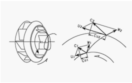
Figure 7 – Velocity Diagram
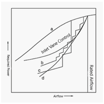
Figure 8 highlights the advantages of inlet vane control over other airflow regulation methods. The key benefits include:
- Wider control range than damper-based control
- Higher efficiency than speed control in certain operating ranges (approximately 70% to 100% of rated airflow)
- More economical operation, especially when combined with other control systems (e.g., system C)
- Simpler structure and lower equipment costs
- Ease of operation and compatibility with remote and automated control systems
- Instant response, meaning there is no delay between operation and effect, making automatic control highly effective
Example of a Structure Used by Osaka Blower
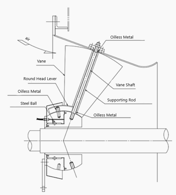
Figure 9 illustrates a specific inlet vane control system structure adopted by Osaka Blower. This system features:
- A unique spherical-link mechanism that enables smooth movement
- All sliding components in full surface contact to ensure proper lubrication
- Use of oil-less metal bearings in locations where lubrication is difficult
- Minimized operating torque and reduced wear, ensuring long-term durability
The standard system shown in the image features an internal drive mechanism. However, in cases where the mechanism is exposed to hot airflow, abrasive environments, or corrosive gases, an external drive system is used to prevent damage.
Performance Characteristics of Inlet Vane Control (Figure 10)
The curve in Figure 10 represents performance changes for different vane opening angles. For convenience, the rated airflow, pressure, and power input are normalized to 100% at the standard operating point.
As shown in the figure, the effect of the inlet vanes begins to become significant at approximately 60 to 70–80 degrees of vane opening. Due to this, the typical operating range of inlet vanes is from 0 degrees to about 70–80 degrees.
For large-capacity fans, fans with frequent or significant partial-load operation, or applications where power consumption is restricted, inlet vane control is highly recommended for efficient performance and energy savings.
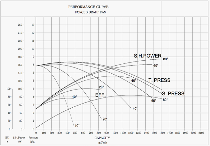
Figure 10
Related Products
REQUEST QUOTATION

PAYMENT

LINK


