③ Indication of light-reception level for simple beam alignment
Color indication of beam status for quick and easy beam adjustment.
Equipped with an Area Beam Indicator (ABI) that notifies the light reception status at a glance. In addition to the ON/OFF status of the light curtain, low light intensity can be checked. The ABI also facilitates simple beam alignment for long-distance sensing. Reduce time for beam alignment and set-up.
④ The light curtain status can be checked at a glance by LED indicators
Even inexperienced operators can easily check status and replace light curtains.
No special skills required for maintenance.
Easy error diagnosis with clear color indicators.
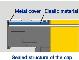
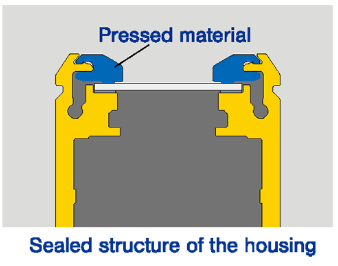
⑤ Metal housing increases ruggedness
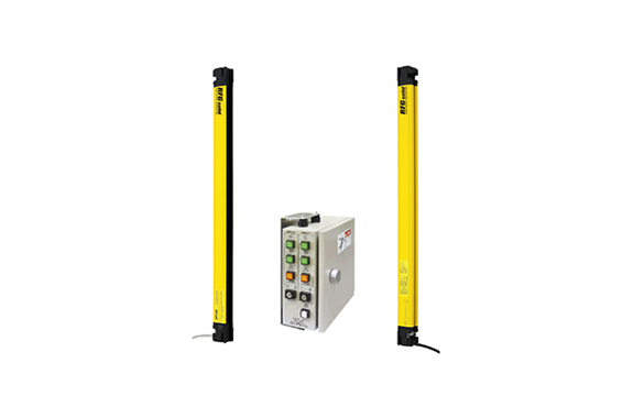
RFG eliminates the dead space that conventionally occurs when light curtains are connected in series or arranged in a U-shape, making it possible to build a system with higher safety.
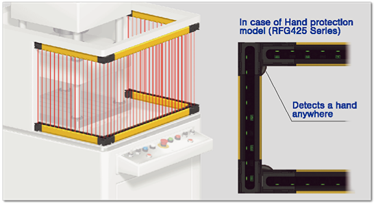
Blanking functions to improve work efficiency while ensuring safety
When stationery objects (e.g., device or material) or moving materials in the sensor monitoring area interrupt beam(s) of the light curtain, press operations can be performed without compromising safety by using blanking functions (fix-blanking, floating blanking)
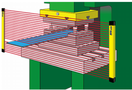
Floating blanking
In normal sensor operation, a signal to stop the press is output if one beam is blocked, but using this function, a stop signal is only sent when two or more beams are blocked. This is useful when it is necessary to move objects in the sensor monitoring area.
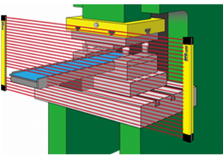
Fixed blanking
Fix blanking is a function that disables the interrupted optical axis monitoring when a specific optical axis is constantly shaded by stationary obstacles (such as equipment or materials), enabling efficient press operations without compromising safety.
*A dedicated controller (optional) is required to use this function. (Available soon)
Diverse line-up to cope with various usage environments
Select the optimal safety light curtain according to the installation environment, type of press and work content.

Specifications

Standard specifications 414Series/425Series/445Series
| RFG414-□□□ | RFG425-□□□ | RFG445-□□□ |
|---|
| Number of beams | 15~199 | 8~124 | 6~38 |
|---|
| Protective height | 140~1980mm | 140~2460mm | 200~1480mm |
|---|
| Beam spacing | 10mm | 20mm | 40mm |
|---|
Minimum object sensitivity
(MOS) | 14mm | 25mm | 45mm |
|---|
| Detection distance | 0.3~10 m | 0.3~20 m | 0.3~20 m |
|---|
Common Specifications
| Response time | ON→OFF:10ms~21ms or less (When a Control Box is used: add 10ms.)
OFF→ON:50ms~105ms or less(When a Control Box is used: add 10ms.) |
|---|
| Power supply voltage (Vs) | When a Control Box is used: 90VAC ~240VAC
Power supply to emitter/receiver: 24VDC±20% (ripple p-p10% or less) |
|---|
| Current consumption | CB6-S:16.8W、CB6-W:30W(Current consumption of emitter/receiver: see other data sheet) |
|---|
| Light source | Infrared LEDs(Wavelength: 870nm) |
|---|
| Safety outputs (OSSD) | PNP transistor x 2, Load current: 300 mA or less, Residual voltage: 2V or less. (except influence drop due to cable extension)
Capacitive load: 1μF max., Leakage current: 1 mA or less
The load current is 150 mAor less in 2-segment cascade and 80 mA or less in 3-segment cascade. |
|---|
| Inverted output (Non-safety output) | PNP transistor x 1, Load current: 100 mA or less, Residual voltage: 2V or less. (except influence drop due to cable extension) |
|---|
| Effective aperture angle | 2.5° max. * Emitter and receiver at operating range of 3 m or greater. |
|---|
| Ambient temperature | Operating: -30~55℃((non-icing), Strage: 30~70℃ |
|---|
| Ambient humidity | Operating: 35% to 85%RH (non-condensing), Strage: 35~95%RH |
|---|
| Ambient illuminance | Incandescent lamp: 3,000 Ix max. on receiver surface, Sunlight: 10,000 Ix max. on receiver surface |
|---|
| Insulation resistance | 20 M or higher (500 VDC megger) |
|---|
| Withstand voltage | 1,000VAC, 50/60Hz for 1 minute. |
|---|
| Degree of protection | IP69K (ISO 20653)IEC 60529: IP65 and IP67 |
|---|
| Vibration resistance | Multiple amplitude of 0.7 mm, 20 sweeps for all 3 axes |
|---|
| Shock resistance | 100 m/s2, 1000 shocks for all 3 axes |
|---|

