Manufacturer : Ross Asia
Model : No.W70
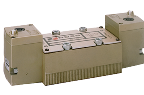
ANSI Valves W70 Series Product Overview
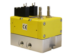
The ROSS ® ANSI valves W70 Series are base mounted spool and sleeve valves that conform to the American National Standards Institute (ANSI) standards for valve-to-base interface configurations, including plug-and-socket electrical connections between valve and base.
These ANSI Size 1, 2.5, 4, 10, and 20 valves are available as, 2- and 3-position, 5-ported 4-way solenoid pilot or pressure controlled valves with either internal or external pilot supply. The spool and sleeve design means there are no seals to wear out.
| Solenoid Pilot Controlled | Direct Solenoid Controlled | Pressure Controlled |
|---|
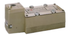 | 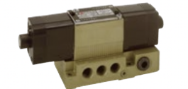 | 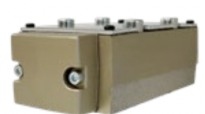 |
Features
| Spool Design | Spool and Sleeve construction for high dirt tolerance |
|---|
| Mounting Options | Individual sub-base or manifold base mounting |
| Pilot Supply | Internal or external; suitable for vacuum service (with external pilot supply) |
| Pilot Operation | Provides high shifting force with low power consumption |
Specifications
| GENERAL |
|---|
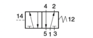
| Function | 5/2 and 5/3 Valve |
| Construction Design | Spool and Sleeve |
| Actuation | Electrical – Solenoid Pilot Controlled
Pneumatic – Pressure Controlled |
| Mounting | Sub-Base or Manifold |
| Connection | Threaded; NPT, G |
| Manual Override | Flush; rubber, non-locking |
| OPERATING CODITIONS | Temperature | Solenoid Pilot Controlled | Ambient | 40 ֯to 120°F (4° to 50°C) |
| Media | 40° to 175°F (4° to 80°C) |
| Pressure Controlled | Ambient | 40° to 175°F (4° to 80°C) |
| Media |
| Flow Media | Filtered air |
| Operating Pressure | Vacuum to 150 psig (Vacuum to 10 bar) |
| Pilot Supply Pressure | ANSI Size | 1 & 20 | Minimum 30 psig (2 bar) |
| 2.5, 4, 10 | Minimum 15 psig (1 bar) |
| External Pilot Supply | Must be equal to or greater than inlet pressure |
| ELECTRICAL DATA FOR SOLENOID PILOT CONTROLLED VALVES | Solenoids | Control | ANSI Size | Current | Operating Voltage | Power Consumption (each solenoid) |
| Solenoid Pilot | 1 | DC | 24 volts | 5 watts |
| AC | 100-110 volts. 50 Hz 100-130 volts. 60 Hz 230-240 volts. 60 Hz | 10 VA inrush. 24 VA holding |
| 2.5, 4, 10, 20 | DC | 24 volts DC | 14 watts |
| AC | 100-110 volts. 50 Hz 100-130 volts. 60 Hz 230-240 volts. 60 Hz | 87 VA inrush. 55 VA holding |
| Direct Solenoid | 1 | DC | 24 volts | 20 watts |
| AC | 110-120 volts. 50/60 Hz 230-240 volts. 60 Hz | 140 VA inrush, 30 VA holding |
| 2.5 & 4 | DC | 24 volts | 20 watts |
| AC | 110-120 volts. 50/60 Hz 230-240 volts. 60 Hz | 380 VA inrush, 79 VA holding |
| Rated for continuous duty |
| ANSI Size 4, 10, & 20 | Indicator Light – One per solenoid |
| Construction Material | Component | Material |
|---|
| Construction Material | Valve Body | Cast Aluminum |
| Spool | Stainless Steel |
| Seals | Buna-N |
PRODUCT CREDENTIALS
| Certificate of Compliance | Declaration of Conformity |
|---|
 |  |
Ordering Information
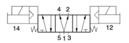
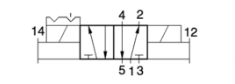
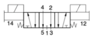
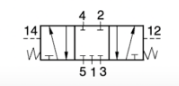
5/2 Single Solenoid Pilot Controlled Valves
| ANSI | Port | Valve Model Number |
|---|
| 24 V DC | 110-120 V AC | 230 V AC |
|---|
| 1 | 1/4 – 3/8 | W7076B2331W | W7076B2331Z | W7076B2331Y |
| 2.5 | 3/8 – 1/2 | W7076A3331W | W7076A3331Z | W7076A3331Y |
| 4 | 3/8 – 3/4 | W7076D4331W | W7076D4331Z | W7076D4331Y |
| 10 | 3/4 – 1-1/4 | W7076C6331W | W7076C6331Z | W7076C6331Y |
| 20 | 1-1/4 – 1-1/2 | W7076C8331W | W7076C8331Z | W7076C8331Y |
| Size | Flow Cv (Nl/min) | Average Response Constants’ | Weight lb (kg) |
| Body | Port 1 | 1-2 | M | F |
| 1-2 | 2-3 |
| 1 | 1/4-3/8 | 1.0 (984) | 20 | 3.6 | 4.9 | 3.0 (1.4) |
| 2.5 | 3/8 -1/2 | 2.5 (2460) | 17 | 1.6 | 2.7 | 3.0 (1.4) |
| 4 | 3/8-3/4 | 4.2 (4133) | 20 | 0.6 | 0.6 | 5.3 (2.4) |
| 10 | 3/4 —1-1/4 | 10(9840) | 30 | 0.3 | 0.3 | 7.3 (3.3) |
| 20 | 1-1/4-1-1/2 | 22 (21648) | 50 | 0.1 | 0.2 | 14.5(6.5) |
Valve Response Time – Response Time (msec) = M + (F • V). This is the average time required to fill a volume V (cubic inches) to 90% of supply pressure or to exhaust it to 10% of supply pressure. M and F values are shown above.
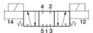
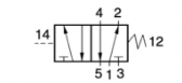
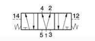
| Valve Schematic |
|---|
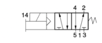 |
Valve Technical Data
| Dimensions -Inches(mm) |
| ANSI Size 1 | 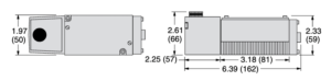 |
| ANSI Size 2.5 | 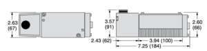 |
| ANSI Size 4 | 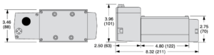 |
| ANSI Size 10 | 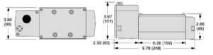 |
| ANSI Size 20 | 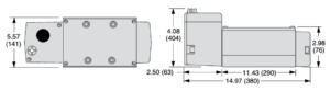 |
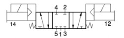
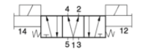
5/2 Double Solenoid Pilot Controlled Valves
| ANSI | Port | Valve Model Number |
|---|
| 24 V DC | 110-120 V AC | 230 V AC |
|---|
| 1 | 1/4 – 3/8 | W7076B2332W | W7076B2332Z | W7076B2332Y |
| 2.5 | 3/8 – 1/2 | W7076A3332W | W7076A3332Z | W7076A3332Y |
| 4 | 3/8 – 3/4 | W7076D4332W | W7076D4332Z | W7076D4332Y |
| 10 | 3/4 – 1-1/4 | W7076C6332W | W7076C6332Z | W7076C6332Y |
| 20 | 1-1/4 – 1-1/2 | W7076C8332W | W7076C8332Z | W7076C8332Y |
| Size | Flow Cv (Nl/mm) | Average Response Constants | Weight lb (kg) |
| Body | Por11 | 1-2 | M | F |
| 1-2 | 2-3 |
| 1 | 1/4 – 3/8 | 0.9 (886) | 20 | 3.6 | 4.9 | 4.0 (1.8) |
| 2.5 | 3/8 -1/2 | 2.0(1968) | 17 | 1.6 | 2.7 | 4.0 (1.8) |
| 4 | 3/8 – 3/4 | 4.2 (4133) | 20 | 0.6 | 0.6 | 6.5 (2.9) |
| 10 | 3/4 -1-1/4 | 11 (10824) | 30 | 0.3 | 0.3 | 9.0 (4.1) |
| 20 | 1-1/4 -1-1/2 | 22 (21648) | 50 | 0.1 | 0.2 | 15.8 (6.8) |
Valve Response Time = Response Time (msec) – M + (F • V). This is the average time required to fill a volume V (cubic inches) to 90% of supply pressure or to exhaust it to 10% of supply pressure. M and F values are shown above.
| Valve Schematic |
|---|
|
| Dimensions -Inches(mm) |
| ANSI Size 1 | 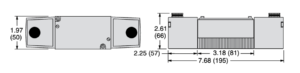 |
| ANSI Size 2.5 | 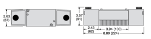 |
| ANSI Size 4 | 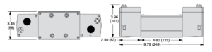 |
| ANSI Size 10 | 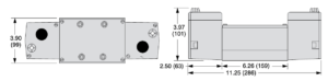 |
| ANSI Size 20 | 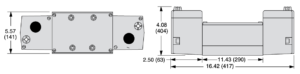 |
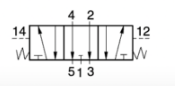
5/3 Double Solenoid Pilot Controlled Valves
| Center Position | ANSI | Port | Valve Model Number |
|---|
| 24 V DC | 110-120 V AC | 230 V AC |
|---|
| Power Center | 1 | 1/4 – 3/8 | W7077B2906W | W7077B2906Z | W7077B2906Y |
| 2.5 | 3/8 – 1/2 | W7077A3904W | W7077A3904Z | W7077A3904Y |
| 4 | 3/8 – 3/4 | W7077C4939W | W7077C4939Z | W7077C4939Y |
| 10 | 3/4 – 1-1/4 | W7077A6920W | W7077A6920Z | W7077A6920Y |
| 20 | 1-1/4 – 1-1/2 | W7077A8901W | W7077A8901Z | W7077A8901Y |
| Closed Center | 1 | 1/4 – 3/8 | W7076B2331W | W7076B2331Z | W7076B2331Y |
| 2.5 | 3/8 – 1/2 | W7076A3331W | W7076A3331Z | W7076A3331Y |
| 4 | 3/8 – 3/4 | W7076D4331W | W7076D4331Z | W7076D4331Y |
| 10 | 3/4 – 1-1/4 | W7076C6331W | W7076C6331Z | W7076C6331Y |
| 20 | 1-1/4 – 1-1/2 | W7076C8331W | W7076C8331Z | W7076C8331Y |
| Open Center | 1 | 1/4 – 3/8 | W7076B2332W | W7076B2332Z | W7076B2332Y |
| 2.5 | 3/8 – 1/2 | W7076A3332W | W7076A3332Z | W7076A3332Y |
| 4 | 3/8 – 3/4 | W7076D4332W | W7076D4332Z | W7076D4332Y |
| 10 | 3/4 – 1-1/4 | W7076C6332W | W7076C6332Z | W7076C6332Y |
| 20 | 1-1/4 – 1-1/2 | W7076C8332W | W7076C8332Z | W7076C8332Y |
| Size | Flow Cv (Nl/min) | Average Response Constants | Weight lb (kg) |
| Body | Port 1 | 1-2 | M | F |
| 1-2 | 2-3 |
| 1 | 1/4-3/8 | 1.0 (984) | 20 | 3.6 | 4.9 | 4.0 (1.8) |
| 2.5 | 3/8-1/2 | 2.5 (2460) | 17 | 1.6 | 2.7 | 4.0 (1.8) |
| 4 | 3/8-3/4 | 4.2 (4133) | 20 | 0.6 | 0.6 | 6.5 (2.9) |
| 10 | 3/4-1-1/4 | 10(9840) | 30 | 0.3 | 0.3 | 8.5 (3.8) |
| 20 | 1-1/4-1-1/2 | 22 (21648) | 50 | 0.1 | 0.2 | 15.3 (6.9) |
Valve Response Time – Response Time (msec) = M + (F • V). This is the average time required to fill a volume V (cubic inches) to 90% of supply pressure or to exhaust it to 10% of supply pressure. M and F values are shown above.
| Valve Schematics |
|---|
| Power Center | Closed Center | Open Center |
|---|
 |  | 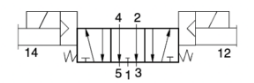 |
| Dimensions -Inches(mm) |
| ANSI Size 1 | 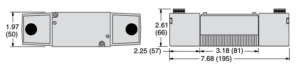 |
| ANSI Size 2.5 | 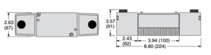 |
| ANSI Size 4 | 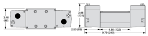 |
| ANSI Size 10 | 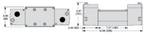 |
| ANSI Size 20 | 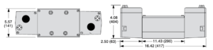 |
5/2 Direct Single Solenoid Pilot Controlled Valves
| Size | Valve Model Number |
| ANSI | Port | Voltage |
| 24 V DC | 110-120 VAC | 230 V AC |
| 1 | 1/4 – 3/8 | W7016B2331W | W701682331Z | W7016B2331Y |
| 2.5 | 3/8- 1/2 | — | W7016A3331Z | W7016A3331Y |
| 4 | 3/8 — 3/4 | — | W7016C4331Z | W7016C4331Y |
| Size | Flow a (Nl/min) | Average Response Constants* | Weight lb (kg) |
| Body | Port 1 | 1-2 | M | F |
| 1-2 | 2-3 |
| 1 | 1/4 – 3/8 | 1.0 (984) | 20 | 3.6 | 4.9 | 35(1.6) |
| 2.5 | 3/8-1/2 | 2.5 (2460) | 17 | 1.6 | 27 | 3.3(15) |
| 4 | 3/8 – 3/4 | 4.2 (4133) | 20 | 0.6 | 0.6 | 43(1.9) |
Valve Response Time – Response Time (msec) = M + (F • V). This is the average time required to fill a volume V (cubic inches) to 90% of supply pressure or to exhaust it to 10% of supply pressure. M and F values are shown above.
| Valve Schematic |
|---|
 |
| Dimensions -Inches(mm) |
| ANSI Size 1 | 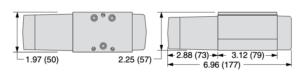 |
| ANSI Size 2.5 | 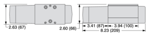 |
| ANSI Size 4 | 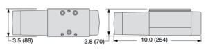 |
5/2 Direct Double Solenoid Pilot Controlled Valves
| Size | Valve Model Number |
| ANSI | Port | Voltage |
| 24 V DC | 110-120 VAC | 230 VAC |
| 1 | 1/4 – 3/8 | W7016B2332W | W7016B2332Z | W7016B2332Y |
| 2.5 | 3/8-1/2 | — | W7016A3332Z | W7016A3332Y |
| 4 | 3/8 – 3/4 | — | W7016C4332Z | W7016C4332Y |
| Size | Flow Cv (Nl/min) | Average Response Constants* | Weight lb (kg) |
| Body | Port 1 | 1-2 | M | F |
| 1-2 | 2-3 |
| 1 | 1/4-3/8 | 1.0 (984) | 20 | 3.6 | 4.9 | 3.5 (1.6) |
| 2.5 | 3/8-1/2 | 2.5 (2460) | 17 | 1.6 | 2.7 | 3.3 (1.5) |
| 4 | 3/8-3/4 | 4.2 (4133) | 20 | 0.6 | 0.6 | 4.3 (1.9) |
Valve Response Time – Response Time (msec) = M + (F • V). This is the average time required to fill a volume V (cubic inches) to 90% of supply pressure or to exhaust it to 10% of supply pressure. M and F values are shown above.
| Valve Schematic |
|---|
 |
| Dimensions -Inches(mm) |
| ANSI Size 1 |  |
| ANSI Size 2.5 | 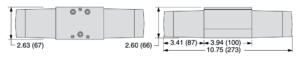 |
| ANSI Size 4 | 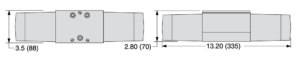 |
5/3 Direct Double Solenoid Pilot Controlled Valves
| Center Position | Size | Valve Model Number |
|---|
| ANSI | Port | 24 V DC | 110-120 V AC | 230 V AC |
|---|
| Power Center | 1 | 1/8 – 3/8 | W7017B2905W | W7017B2905Z | W7017B2905Y |
| 1 | 1/8 – 3/8 | W7017B2331W | W7017B2331Z | W7017B2331Y |
| Closed Center | 2.5 | 3/8 – 1/2 | W7017A3331W | W7017A3331Z | W7017A3331Y |
| 4 | 1/2 – 3/4 | W7017C4331W | W7017C4331Z | W7017C4331Y |
| Open Center | 1 | 1/8 – 3/8 | W7017B2332W | W7017B2332Z | W7017B2332Y |
| 2.5 | 3/8 – 1/2 | W7017A3332W | W7017A3332Z | W7017A3332Y |
| 4 | 1/2 – 3/4 | W7017C4332W | W7017C4332Z | W7017C4332Y |
| Size | Flow Cv (Nl/min) | Average Response Constants* | Weight lb (kg) |
| Body | Port 1 | 1-2 | M | F |
| 1-2 | 2-3 |
| 1 | 1/4-3/8 | 1.0 (984) | 20 | 3.5 | 4.9 | 4.5 (2.0) |
| 2.5 | 3/8-1/2 | 1.9 (1870) | 10 | 1.3 | 1.8 | 5.0 (2.3) |
| 4 | 1/2-3/4 | 3.8 (3739) | — | — | — | 5.8 (2.6) |
Valve Response Time – Response Time (msec) = M + (F • V). This is the average time required to fill a volume V (cubic inches) to 90% of supply pressure or to exhaust it to 10% of supply pressure. M and F values are shown above.
| Valve Schematics |
|---|
| Power Center | Closed Center | Open Center |
|---|
 |  |  |
| Dimensions -Inches(mm) |
| ANSI Size 1 | 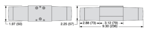 |
| ANSI Size 2.5 | 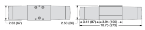 |
| ANSI Size 4 | 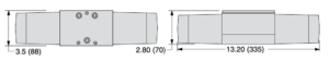 |
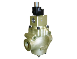
5/2 Single Pressure Controlled Valves
| Size | Valve Model Number |
|---|
| ANSI | Port |
|---|
| 1 | 1/4 – 3/8 | W7056B2331 |
| 2.5 | 3/8 – 1/2 | W7056A3331 |
| 4 | 3/8 – 3/4 | W7056B4331 |
| 10 | 3/4 – 1-1/4 | W7056A6331 |
| 20 | 1-1/4 – 1-1/2 | W7056A8331 |
* Sub-bases and manifold bases ordered separately. Please see Sub-Bases and Manifolds section.
| Size | Flow Cv (Nl/min) | Average Response Constants* | Weight lb (kg) |
| Body | Port 1 | 1-2 | M | F |
| 1-2 | 2-3 |
| 1 | 1/4-3/8 | 1.0 (984) | 20 | 3.6 | 4.9 | 25(1.1) |
| 2.5 | 3/8-1/2 | 2.5 (2460) | 17 | 1.5 | 2.6 | 2.0 (0.9) |
| 4 | 3/8-3/4 | 4.2 (4133) | 12 | 0.6 | 0.7 | 4.3 (1.9) |
| 10 | 3/4-1-1/4 | 10(9840) | 20 | 0.3 | 0.3 | 6.3 (2.8) |
| 20 | 1-1/4 —1-1/2 | 22 (21648) | 30 | 0.1 | 0.2 | 13.0(5.9) |
Valve Response Time – Response Time (msec) = M + (F • V). This is the average time required to fill a volume V (cubic inches) to 90% of supply pressure or to exhaust it to 10% of supply pressure. M and F values are shown above.
| Valve Schematic |
|---|
 |
| Dimensions -Inches(mm) |
| ANSI Size 1 | 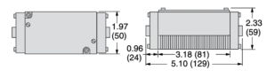 |
| ANSI Size 2.5 | 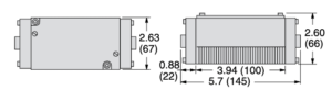 |
| ANSI Size 4 | 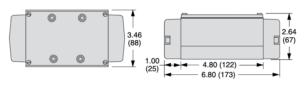 |
| ANSI Size 10 | 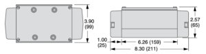 |
| ANSI Size 20 | 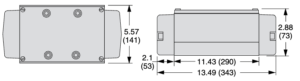 |
5/2 Double Pressure Controlled Valves
| Size | Valve Model Number |
|---|
| ANSI | Port |
|---|
| 1 | 1/4 – 3/8 | W7056B2331 |
| 2.5 | 3/8 – 1/2 | W7056A3331 |
| 4 | 3/8 – 3/4 | W7056B4331 |
| 10 | 3/4 – 1-1/4 | W7056A6331 |
| 20 | 1-1/4 – 1-1/2 | W7056A8331 |
* Sub-bases and manifold bases ordered separately. Please see Sub-Bases and Manifolds section.
| Size | Flow Cv (Nl/min) | Average Response Constants* | Weight lb (kg) |
| Body | Port 1 | 1-2 | M | F |
| 1-2 | 2-3 |
| 1 | 1/4-3/8 | 1.0 (984) | 20 | 3.6 | 4.9 | 25(1.1) |
| 2.5 | 3/8-1/2 | 2.5 (2460) | 17 | 1.5 | 2.6 | 2.0 (0.9) |
| 4 | 3/8-3/4 | 4.2 (4133) | 12 | 0.6 | 0.7 | 4.3 (1.9) |
| 10 | 3/4-1-1/4 | 10(9840) | 20 | 0.3 | 0.3 | 6.3 (2.8) |
| 20 | 1-1/4 —1-1/2 | 22 (21648) | 30 | 0.1 | 0.2 | 13.0(5.9) |
Valve Response Time – Response Time (msec) = M + (F • V). This is the average time required to fill a volume V (cubic inches) to 90% of supply pressure or to exhaust it to 10% of supply pressure. M and F values are shown above.
| Valve Schematic |
|---|
 |
| Dimensions -Inches(mm) |
| ANSI Size 1 | 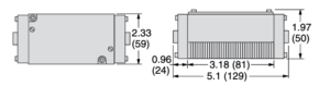 |
| ANSI Size 2.5 | 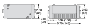 |
| ANSI Size 4 | 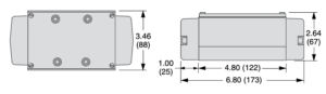 |
| ANSI Size 10 | 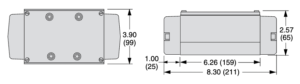 |
| ANSI Size 20 | 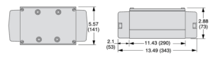 |
5/3 Double Pressure Controlled Valves
| Center Position | Size | Valve Model Number |
|---|
| ANSI | Port | 24 V DC |
|---|
| Power Center | 10 | 3/4 – 1-1/4 | W7057A6902 |
| Closed Center | 1 | 1/4 – 3/8 | W7057B2331 |
| 2.5 | 3/8 – 1/2 | W7057A3331 |
| 4 | 3/8 – 3/4 | W7057B4331 |
| 10 | 3/4 – 1-1/4 | W7057A6331 |
| 20 | 1-1/4 – 1-1/2 | W7057A8331 |
| Open Center | 1 | 1/4 – 3/8 | W7057B2332 |
| 2.5 | 3/8 – 1/2 | W7057A3332 |
| 4 | 3/8 – 3/4 | W7057B4332 |
| 10 | 3/4 – 1-1/4 | W7057A6332 |
| 20 | 1-1/4 – 1-1/2 | W7057A8332 |
* Sub-bases and manifold bases ordered separately. Please see Sub-Bases and Manifolds section.
| Size | Flow Cv (Nl/min) | Average Response Constants* | Weight lb (kg) |
| Body | Port 1 | 1-2 | M | F |
| 1-2 | 2-3 |
| 1 | 1/4 -3/8 | 1.0 (984) | 20 | 3.5 | 4.9 | 2.5 (1.1) |
| 2.5 | 3/8-1/2 | 2.5 (2460) | 17 | 1.5 | 2.6 | 2.0 (0.9) |
| 4 | 3/8-3/4 | 4.2(4133) | 12 | 0.6 | 0.7 | 4.3 (1.9) |
| 10 | 3/4-1-1/4 | 10(9840) | 20 | 0.3 | 0.3 | 6.3 (2.8) |
| 20 | 1-1/4 -1-1/2 | 22 (21648) | 30 | 0.1 | 0.2 | 13.8 (6.2) |
Valve Response Time – Response Time (msec) = M + (F • V). This is the average time required to fill a volume V (cubic inches) to 90% of supply pressure or to exhaust it to 10% of supply pressure. M and F values are shown above.
| Valve Schematics |
|---|
| Power Center | Closed Center | Open Center |
|---|
 |  |  |
| Dimensions -Inches(mm) |
| ANSI Size 1 | 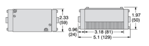 |
| ANSI Size 2.5 | 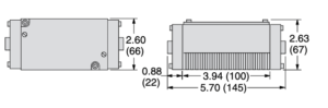 |
| ANSI Size 4 | 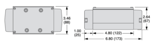 |
| ANSI Size 10 | 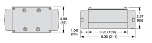 |
| ANSI Size 20 |  |