- Home
- Products
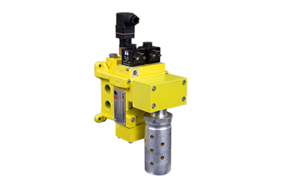
- Ross Asia DMC1 series double valve Safety cat. 4 PL e, internal monitoring, automatic reset
Japan, Ross Asia
Ross Asia DMC1 series double valve Safety cat. 4 PL e, internal monitoring, automatic reset
Made in Japan
Manufacturer : Ross Asia
Model: DMC1 series double valve
Safe Exhaust Control Reliable Double Valves DM 1 Series C Product Overview
Safe Exhaust Safety Function
| Feature | Description |
|---|---|
| Redundant Control | Redundant control can achieve Category 4, PL e, when used with proper safety controls |
| Dynamic Monitoring | Two identical valve elements integrate monitoring and air flow control functions for Category 4 applications. The valve exhausts downstream air if asynchronous movement of valve elements occurs during actuation or de-actuation, resulting in a residual outlet pressure of less than 1% of supply. If the abnormality clears itself, the valve will return to the ready-to-run state; there is no memory of the abnormal behavior, as in the ROSS DM²® Series C products that require an intentional reset following lockout. |
| Poppet Design | Dirt tolerant, wear compensating for quick response and high flow capacity |
| PTFE Backup Piston Rings | Enhances valve endurance enabling operation with or without in-line lubrication |
| Ready-to-run | If an abnormality clears itself upon the removal of electricity to both solenoids, it will be ready-to-run again. It does not remember the abnormality and stay in a locked-out state until intentionally reset. Therefore, cumulative abnormalities may go undetected. |
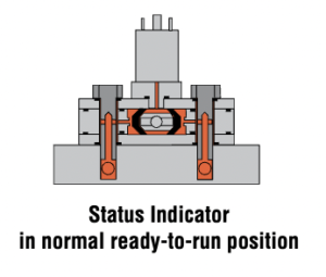
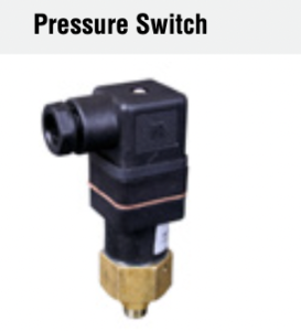
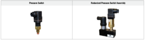
| Status Indicator | It includes a pressure switch with normally open (NO) and normally closed (NC) contacts to signal the control system about the valve’s “ready-to-run” status or abnormal function. Integration with machine controls is necessary to block a run signal until clearing the valve’s fault. This indicator only reports status and does not function as part of a lockout. |
| Silencer | Includes high flow, clog resistant silencer |
| Mounting | Inlet and outlet ports on both sides provide for flexible piping (plugs for unused ports included); captive valve-to-base mounting screws |
| Flexible Piping | Inlet and outlet ports on both sides (plugs for unused ports included) |
| SISTEMA Library | Available for download |
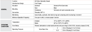
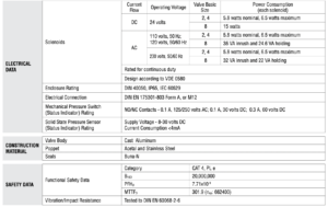
Specifications
PRODUCT CREDENTIALS
Ordering Information
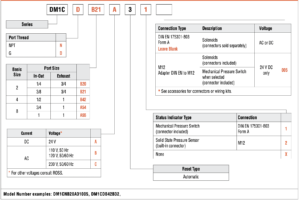
MODEL NUMBER CONFIGURATOR(3-Way 2-Position Valves)
Safety Solutions Options
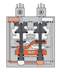
Valve Operation
Orifices restrict the flow of inlet air pressure from the inlet chamber into the crossover passages, allowing air pressure to bypass the lower inlet poppets. Flow is sufficient to quickly pressurize the pilot supply/timing chambers on both sides A and B. The upper inlet poppets prevent air flow from the crossover passages into the outlet chamber. Air pressure acting on the inlet poppets and return pistons securely hold the valve elements in the de-actuated position. | |
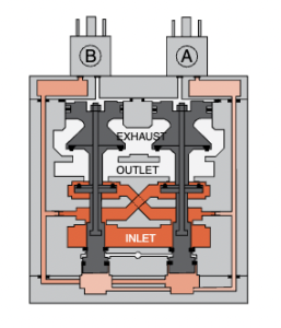 | |
| Valve Actuated | Energizing the pilot solenoids simultaneously applies pressure to both pistons, moving internal parts to their actuated position, opening inlet air flow to outlet and closing both exhaust poppets. Simultaneously energizing the pilot solenoids applies pressure to both pistons, moving internal parts to actuated positions, thereby opening the inlet air flow to the outlet and closing both exhaust poppets. De-energizing the main solenoids causes the valve elements to return to the ready-to-run (de-actuated) position. |
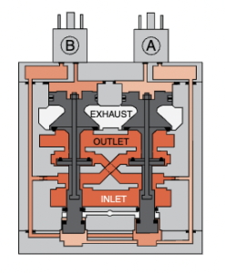 | |
| Asynchronous Operation | If valve elements actuate asynchronously enough, the valve shifts into a position where it exhausts one crossover and its timing chambers, while pressurizing the other crossover and its timing chambers. In the illustration, side B is in the de-actuated position, but has no pilot air available to actuate with and has full pressure on its upper and lower inlet poppets and return piston to hold it in place. Inlet air flow into side B’s crossover is restricted, flowing through side A’s open upper inlet poppet, then through the outlet to the exhaust port, and finally from the exhaust port to the atmosphere. Residual pressure in the outlet is less than 1% of inlet pressure. Once the main solenoids are de-energized, they remove actuating pressure from the top of the main pistons. Then, the lower inlet poppet return spring and inlet air pressure acting on the side A return piston push side A back into the de-actuated position. Inlet air pressurizes the crossovers and volume chambers. Pressure in the crossovers helps hold the upper inlet poppets on seat. The valve will then be in the ready-to-run position. On the next attempt to actuate normally, if side B is still unable to actuate synchronously with side A, the same sequence of events described above will occur again . |
 | |
| Status Indicator | The status indicator pressure switch will actuate when the main valve is operating normally, and will de-actuate when the main valve operation is sufficiently asynchronous or inlet pressure is removed. This device is not part of the valve lockout function, but, rather, only reports the status of the main valve. |
 |
Valve Technical Data
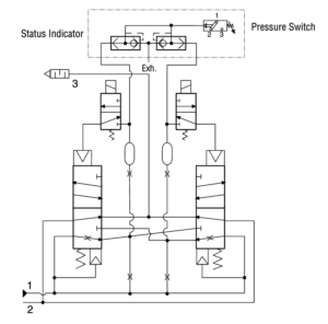
Valve Schematic
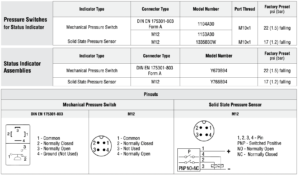
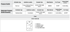
| Solenoid & Pressure Switch Pinouts | ||
| Solenoid | DIN EN 175301-803 Form A | 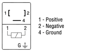 |
| M12 | 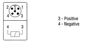 | |
| Pressure Switch | DIN EN 175301-803 Form A | 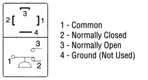 |
| M12 | 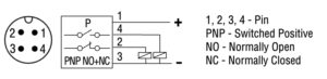 | |
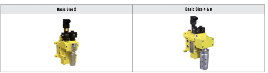
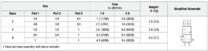
| Dimensions-Inches(mm) | ||
| Basic Size | Port Size | View X (base mounting hole pattern) |
| 2 | 1/4 & 3/8 | 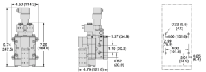 |
| 4 | 1/2 | 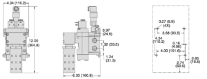 |
| 8 | 3/4 & 1 | 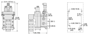 |

Accessories
ELECTRICAL STATUS INDICATION
ENERGY RELEASE VERIFICATION
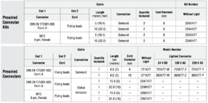
PREWIRED ELECTRICAL CONNECTORS

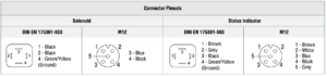
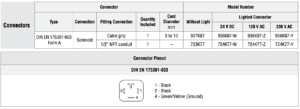
ELECTRICAL CONNECTORS

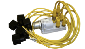
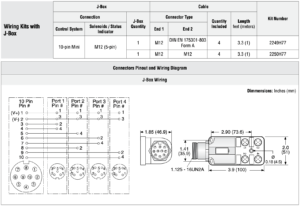
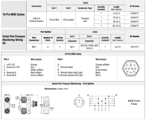
JUNCTION BOX OPTIONS
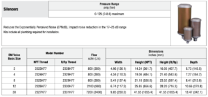
HIGH FLOW NOISE REDUCTION SILENCER KITS
Related Products

REQUEST QUOTATION

PAYMENT

LINK


