Japan, Ross Asia
Ross Asia Serial bus Uses ROSS & Turck modular I/0

Made in Japan
Manufacturer :Ross Asia
Model : Serial bus
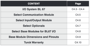
ROSS Serial Bus System with TURCK Modular I/O – KEY FEATURES
- A complete Centralized Serial Bus communication offering for ISO valves W65 and W66 Series.
- I/O system based on the TURCK Modular Industrial I/0 System BL 67.
- Communication module supports up to 32 station modules each supporting up to 8 I/O modules.
- Input modules accept signals from sensors, photo eyes, limits and other field input devices.
- Output modules provide signals to remote solenoid valves and other field output devices.
- UL, C-UL, and CE certified.
Modular Industrial I/O System BL 67
TURCK Serial Bus System
The BL67 Solution
BL67 combines all the flexibility of an in-the-cabinet PLC I/O system with modularity, ruggedness and connectorization.
BL67 complements the AIM™, BL20 and piconet ® product families to meet the needs of unique applications, such as small machine or conveyor systems requiring IP 67 protection.
The BL67 Concept
The BL67 modular concept is a very flexible approach to connectorized I/O. The gateway, base and electronic modules provide many benefits to the user.
- The gateway provides communication between the fieldbus and I/O modules; modules are not dependent on the fieldbus protocol.
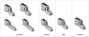
- DIN-rail or frame mountable base modules are available with eurofast ® (M12), minifast ® (7/8-16UN), M23 and picofast ® (M8) connectors.
- Electronic modules are hot swappable•
- Power distribution module (24 volts DC) supplies the connected I/O signals
BL67’s openness, flexibility, connectorization, compact housing and ruggedness provide a viable alternative to in-the cabinet I/O.
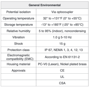
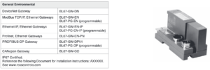
Environmental Conditions
Intended Application Environments
- BL67 does not need an enclosure
- Mount directly on machine or conveyor
- Rugged design provides protection against dirt, dust and liquids
Not intended for These Environments
- Continuous submersion
- 100 percent humidity
- High pressure washdown
Note: For higher levels of protection consider fully potted AIM stations
Maximum Size of a BL67 Station
BL67 stations consist of a gateway and a maximum of 32 modules (equivalent to 1 m station length). Some high-tech and analog I/O modules may consume or produce large amounts of data, and therefore may limit the number of modules that may be used per system. It is highly recommended that the I/O assistant software is used when planning and commissioning BL67 systems. This program allows you to build the BL67 node on your computer and verify that all restrictions with regard to power and size are met. The free I/O assistant software is available for download from www.turck.com.
Addressing
As a node on a network, BL67 stations are addressed dependent on the network system being used. Each network gateway has a set of rotary switches used to set the address for the node. DeviceNet™ and CANopen gateways may be addressed between 0 and 63 via two switches (one for the 10’s digit and one for the 1’s digit). For example, to set the address to 37 you would set the 10’s switch to 3 and the 1’s switch to 7. The third switch on the gateway may be used to set the communication rate of the network interface. PROFIBUS ® -DP gateways may be set from 1 to 125 by using three switches (one for the 100’s, one for the 10’s and one for the 1’s).
Ethernet gateways allow different addressing schemes depending on the Ethernet addressing method being used in the overall system.
Dynamic addressing schemes include BootP and DHCP, while hard-coding a static address is also allowed. TURCK Serial Bus System Modular Industrial I/O System BL 67.
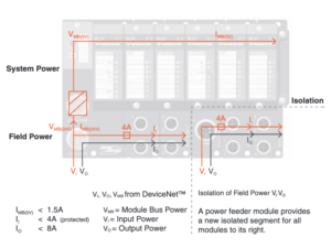
BL67 Power Distribution
Power Overview
The power supply for a BL67 station is fed via the power connector on the PROFIBUS ® gateway or directly from the network on the DeviceNet™ gateway. Power feeder modules can be added to the system at any point to provide a fresh isolated supply of power to all I/O connected to its right.
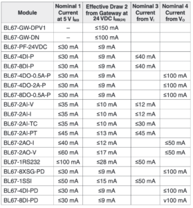
Internal Power Consumption via Module Bus
The amount of BL67 modules that may be supplied via the internal module bus depends on the respective nominal current IMB of the individual modules on the module bus. The sum of the nominal current inputs of the connected BL67 module must not exceed 1.5 A. If the I/O assistant software is used, an error message is generated automatically via the <Station – Verify> as soon as the system supply via the module bus is no longer sufficiently guaranteed.
To calculate current draw on DeviceNet: Add IMB(24) for all modules. Then add VI and VO for electronic modules to the left of the first power feed module. Next, add the current draw of the I/O devices.
To calculate current draw on PROFIBUS gateway power connector for VI: Add IMB for all modules. Then add VI current for all modules to the left of the first power feed module. Next, add the current draw of the input devices.
For VO, add the VO current for all modules to the left of the first power feed module. Next, add the current draw of the output devices.
VMB = Module bus power
VI = Input power
VO = Output power
IMB = Module bus current
IMB(24) = Effective current draw from gateway at 24 volts DC supply.
Applying Power to BL67
PROFIBUS ®, Ethernet and CANopen System
DeviceNet TM System

Electrical:
- Operating Current: <600 mA from V MB
- Input Supply Current: <4 A (from V I )
- Output Supply Current: <8 A (from V O )
- Backplane Current: <1.5 A (from V MB)
Mechanical:
- Operating Temperature: -12 to +55°C (-13 to +131°F)
- Protection: IP 67
- Vibration: 5 g @ 10-500 Hz
Material:
- Housing: PC-V0 (Lexan)
Diagnostics (Logical)
- Diagnostic information available through the DeviceNet I/O map
Diagnostics (Physical)
- LEDs to indicate status of DeviceNet and Module Bus communication
Programmability
- PG in model number designates a programmable gateway
- Progammable according to IEC 61131.3 using CodeSy (includes ladder logic)
- Use CodeSys to create logic programs to control local I/O
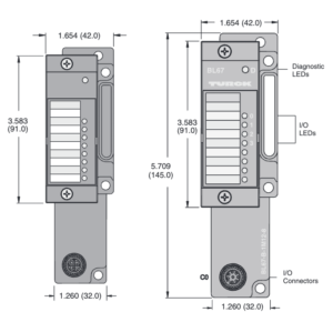
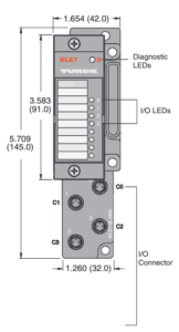
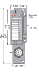
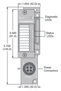
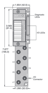
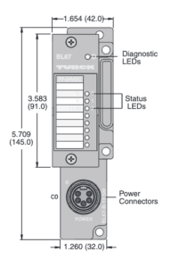
Dimensions – inches (mm) 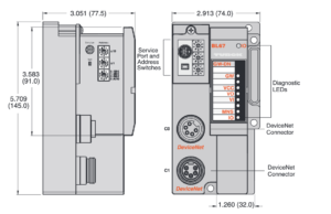
Step 2
Select Input/Output Module
Power Distribution
Inputs: V1
Outputs: V0
Logic: VMB
Mechanical:
Operating Temperature: +32 to +131°F (0 to +55°C)
Protection: NEMA 1,3,4,12,13 / IEC IP 67
Vibration: 5 g @ 10 – 500 Hz
Material:
Connectors: Nickel-plated brass
Housing PC-VO (Lexan)
Diagnostics (Logical)
Diagnostic information available through the fieldbus gateway
Diagnostics (Physical)
LEDs to indicate status of DeviceNet and Module Bus communication
LEDs for each I/O point to indicate on/off status


Step 3
Select Optionals
Select Optional CANopen Interface / Serial Communication Modules
Power Distribution
Inputs: V1
Outputs: V0
Logic: V MB
Mechanical:
Operating Temperature: +32 to +131°F (0 to +55°C)
Protection: NEMA 1,3,4,12,13 / IEC IP 67
Vibration: 5 g @ 10 – 500 Hz
Material:
- Connectors: Nickel-plated brass
- Housing: PC-VO (Lexan)
Diagnostics (Logical)
- Diagnostic information available through the fieldbus gateway
Diagnostics (Physical):
- LED to indicate module bus communication status as well as I/O diagnostics
- LEDs for each I/O point to indicate on/off status
Functional Description
- Connect up to 8 CANopen slaves to this module
- Map the slaves into any available fieldbus


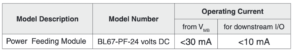
Select Optional CANopen Interface / Serial Communication Modules
Electrical:
Operating CurrentInputs: V1
Outputs: V0
Logic: VMB
Power Distribution:
Accepts 24 volts DC supply to provide V1 and V0 for downstream modules
Material:
Connectors: Nickel-plated brass
Housing PC-VO (Lexan)
Diagnostics (Logical)
Diagnostic information available through the fieldbus gateway
Diagnostics (Physical)
LEDs to indicate status of DeviceNet and Module Bus communication
LEDs for each I/O point to indicate on/off status

Step 6
Select Base Modules for BL67 I/O

Labels for labeling electronic modules
BL67-Label/DIN-A4-50-PCS
Programming Cable –
For connecting the BL20/BL67 system to
the I/O Assistant software
XN-PS2-CABLE
 DIN A4 sheet size
Base Module Dimensions and Pinouts
| Dimensions – inches (mm) | |||
| eurofast® | picofast® | M23 | minifast |
 |  |  |  |
 |  |  | |
Related Products


REQUEST QUOTATION

PAYMENT

LINK


