Japan, Ross Asia
Ross Asia SERPAR® 35 Series Double valve with electropneumatic EP monitor
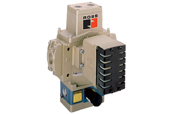
Made in Japan
Manufacturer : Ross Asia
Model : SERPAR® 35 Series
SERPAR ® Double Valves with E-P Monitor 35 Series Product Overview
Clutch/Brake Control Function
The SERPAR ® E-P double valve is designed to provide control of clutch/brake mechanisms on mechanical stamping presses as well as other safety applications, such as alternative lockout systems for energy isolation.
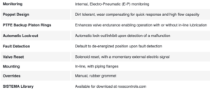
The SERPAR ® Series valves are internally monitored double valves with a built-in monitoring device that checks for the proper operation of each valve element. If the internal monitor detects a valve fault on a particular cycle, the double valve will fail to a safe condition (all downstream air is exhausted) and the monitor will lock-out to inhibit further operation of the device. Normal operation can only be resumed by a momentary reset signal to the valve.
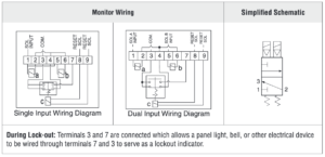
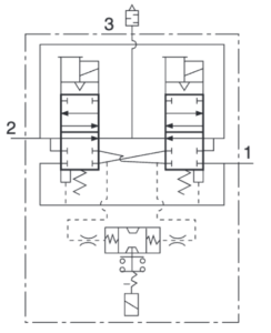
Valve models with E-P monitor are available with Single Input Signal and Dual Input Signal. Single Input valves require only one main solenoid signal wired into the terminal strip of the E-P monitored double valve. The main solenoid
signal is wired into terminal 1 and internally jumpered to the second main solenoid. Commons are wired into terminal 3. This allows both solenoids to be energized and de-energized simultaneously for proper valve operation.
Dual Input valves require two solenoid signals wired independently into the terminal strip of the E-P monitored double valve. One main solenoid signal is wired into terminal 1 and the second main solenoid signal is wired into terminal 5. Commons are wired into terminal 3. Both solenoid signals must arrive simultaneously for proper valve operation.
VALVE FEATURES
Specifications

PRODUCT CREDENTIALS

Ordering Information
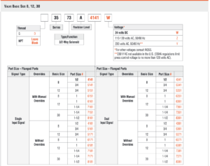
MODEL NUMBER CONFIGURATOR(3-Way 2-Position Valves)
| Valve Schematic |
 |
Valve Operation
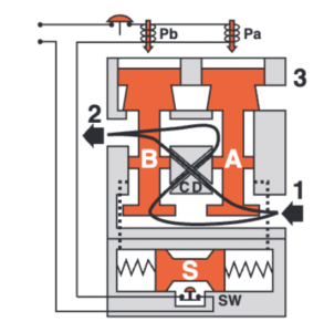
| Conditions at Start | Inlet 1 is closed to outlet 2 by both valve elements A and B. Outlet 2 is open to exhaust 3. Contacts of switch SW are closed. Monitoring pressure signals at both ends of spool S are exhausted. |
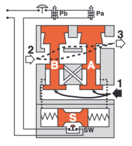 | |
| Normal Operation | Simultaneously energizing both solenoids actuates both pilots and causes valve elements A and B to shift. Inlet 1 is then connected to outlet 2 via crossflow passages C and D. Exhaust 3 is closed. Monitoring pressure signals go to each end of spool S and become equal to inlet pressure. |
 | |
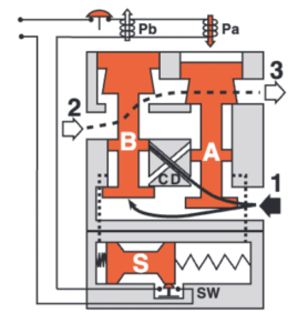
| Detecting a Malfunction | A malfunction in the system or the valve itself could cause one valve element to be open and the other closed. Air then flows past the inlet poppet on valve element A, into crossflow passage D, but is substantially blocked by the spool portion of element B. The large size of the open exhaust passage past element B keeps the pressure at the outlet port below two percent of inlet pressure. Full monitoring air pressure from side A goes to the right end of spool S, and a reduced pressure goes to the left end. This pressure imbalance causes the spool to shift to the left. This trips switch SW, breaks the electrical circuit to the pilot solenoids, and allows valve element A to return to the closed position. |
 | |
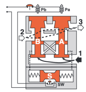
| E-P Monitor Locked-out | With both valve elements closed, monitoring air pressure is exhausted from both ends of spool S so that it returns to its normal position. The electrical circuit to the pilot solenoids remains broken by switch SW. To restore the electrical circuit and return the valve to normal operation, the reset solenoid (not shown) must be briefly energized to reset switch SW. During and following reset, the pilot solenoids must be kept de-energized to prevent inadvertent and possibly dangerous cycling of the press. Prolonged energizing of the reset solenoid can cause burnout and nullify the reset function. |
 |
Both solenoids must be energized simultaneously to shift the valve; maintained signal required to keep valve shifted.
WARNING: If monitor must be reset, electrical signals to both solenoids must be removed to prevent the machine controlled by the valve from immediately recycling and producing a potentially hazardous condition.
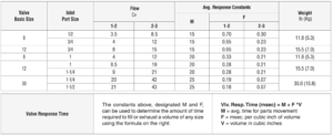
Valve Technical Data
| Dimensions-Inches(mm) | |
| Basic Size 8 |  |
| Basic Size 12 | 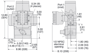 |
| Basic Size 30 | 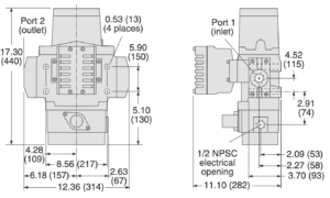 |
Accessories & Options
ENERGY RELEASE VERIFICATION

REPLACEMENT VALVES
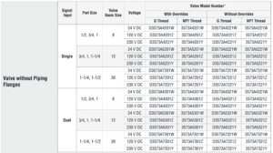
CONNECTION PIPING KITS

Related Products
-
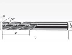
Okazaki Seiko CHRS / CHRSM Solid Carbide Short Helical Reamers
-
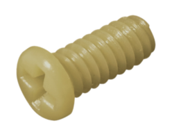
Nippon Chemical Screw PEEK/MPH(M-L) PEEK/Micro (+) pan head machine screw
-
SANYUTEC KHS-Type Universal Joint With Spline Shaft And Needle Bearings
-
KETT ELECTRIC LABORATORY PDL-01 Data Logger Software
-

Okamoto Tape
-
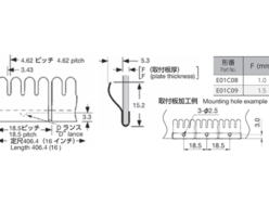
Seiwa E01C08 Clip-on Mounting EMC Products


