Sakai
Sakai LAD-C Series Precision Spring Coupling
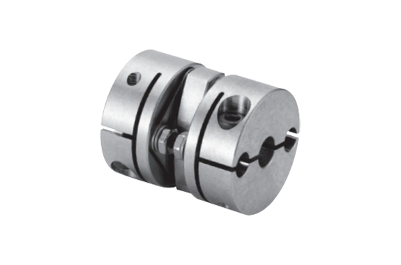
Manufacturer: Sakai Manufacturing Co., Ltd.
Model: LAD-C Series
Features
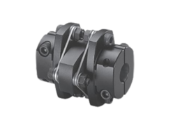
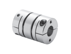
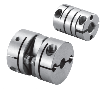
- A unique laminated leaf spring with excellent precision and rigidity has used as the flexure material. Two sets of laminated leaf springs attached to the hub with bolts and high flexibility create a non-backlash structure, achieving high precision and high torque rotation transmission.
- Two sets of laminated leaf springs sandwiched between spacers absorb eccentricity, angular misalignment, and axial displacement. This precision shaft coupling combines high versatility with high flexibility, easy centering, and high precision rotation transmission.
Specifications
(Dimensions: mm)
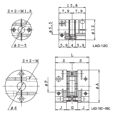
| Model number | d | A | P | L | S | J | G | M |
|---|---|---|---|---|---|---|---|---|
| LAD-12C | See LAD-12C dimensional drawing | |||||||
| LAD-15C | 3~5 | 15 | 3.5 | 20 | 10 | 7.7 | 4.6 | M2 |
| LAD-20C | 4~8 | 20 | 5.5 | 24 | 12 | 8.9 | 6.2 | M2.5 |
| LAD-25C | 6~10 | 25 | 7.5 | 30 | 15 | 11 | 8 | M3 |
| LAD-30C | 6~14 | 30 | 11.5 | 31 | 15.5 | 11.5 | 8 | M3 |
| LAD-35C | 8~16 | 35 | 12.5 | 35 | 17.5 | 12.5 | 10 | M3 |
| LAD-40C | 10~20 | 40 | 16 | 40 | 20 | 14.6 | 10.8 | M3 |
| LAD-48C | 10~24 | 48 | 18 | 52 | 26 | 17 | 18 | M4 |
| LAD-58C | 12~25 | 58 | 21 | 60 | 30 | 20 | 20 | M5 |
| Model number | Allowable torque N・m | Allowable eccentricity mm | Allowable deviation angle ° | Allowable axial displacement mm | Maximum rotation speed min-1 | Torsional stiffness | Axial spring constant N/mm | Moment of inertia kg・m2 | Mass g | |
|---|---|---|---|---|---|---|---|---|---|---|
| Overall N・m/rad | Leaf spring only N・m/rad | |||||||||
| LAD-12C | 0.25 | 0.03 | 0.5 | ±0.08 | 10000 | 132 | 200 | 10 | 0.08×10⁻⁶ | 4 |
| LAD-15C | 0.6 | 0.03 | 0.5 | ±0.09 | 10000 | 196 | 700 | 88 | 0.25×10⁻⁶ | 8 |
| LAD-20C | 1.3 | 0.09 | 1 | ±0.25 | 10000 | 490 | 1200 | 39 | 0.92×10⁻⁶ | 17 |
| LAD-25C | 2.8 | 0.12 | 1 | ±0.31 | 10000 | 882 | 1850 | 25 | 2.69×10⁻⁶ | 32 |
| LAD-30C | 3.6 | 0.12 | 1 | ±0.39 | 10000 | 1470 | 4300 | 15 | 5.76×10⁻⁶ | 44 |
| LAD-35C | 5 | 0.14 | 1 | ±0.46 | 10000 | 2940 | 5400 | 25 | 1.19×10⁻⁵ | 68 |
| LAD-40C | 6 | 0.15 | 1 | ±0.55 | 10000 | 3920 | 6300 | 20 | 2.28×10⁻⁵ | 96 |
| LAD-48C | 12 | 0.23 | 1 | ±0.65 | 10000 | 6000 | 12800 | 29 | 0.57×10⁻⁴ | 172 |
| LAD-58C | 25 | 0.27 | 1 | ±0.79 | 10000 | 12000 | 25700 | 29 | 1.48×10⁻⁴ | 317 |
*Select the LAD-20LS model for a non-standard through-hole diameter or insufficient insertion depth in the LAD-20C model to a wide mounting interval.
Standard Shaft Hole Diameter
(Unit: mm)
| Model number | d | |||||||||||||||||||||
|---|---|---|---|---|---|---|---|---|---|---|---|---|---|---|---|---|---|---|---|---|---|---|
| 3 | 4 | 4.5 | 5 | 6 | 6.35 | 7 | 8 | 9 | 9.525 | 10 | 11 | 12 | 14 | 15 | 16 | 18 | 19 | 20 | 22 | 24 | 25 | |
| LAD-12C | ● | ● | – | ● | – | – | – | – | – | – | – | – | – | – | – | – | – | – | – | – | – | – |
| LAD-15C | ● | ○ | ○ | ○ | ○ | – | – | – | – | – | – | – | – | – | – | – | – | – | – | – | – | – |
| LAD-20C | – | ● | ● | ● | ○ | ○ | 🟤 | ○ | – | – | – | – | – | – | – | – | – | – | – | – | – | – |
| LAD-25C | – | – | – | – | ● | ● | ● | ☆ | ○ | ○ | ○ | – | – | – | – | – | – | – | – | – | – | – |
| LAD-30C | – | – | – | – | ● | ● | ● | ● | ● | ● | ● | ● | ○ | ○ | – | – | – | – | – | – | – | – |
| LAD-35C | – | – | – | – | – | – | – | ● | – | ● | ● | ● | ● | ○ | ○ | ○ | – | – | – | – | – | – |
| LAD-40C | – | – | – | – | – | – | – | – | – | – | ● | ● | ● | ● | ● | ○ | ○ | ○ | ○ | – | – | – |
| LAD-48C | – | – | – | – | – | – | – | – | – | – | ● | ● | ● | ● | ● | ● | ○ | ○ | ○ | ○ | ○ | – |
| LAD-58C | – | – | – | – | – | – | – | – | – | – | – | – | ● | ● | ● | ● | ● | ● | ● | ○ | ○ | ○ |
- LAD-58C is not a standard product (delivery confirmation product).
- Permissible radial direction variation does not occur misalignment and tilt angle are zero.
- Permissible misalignment angle limits with simultaneous misalignment and tilt angle.
- Moment of inertia and mass apply only to the maximum shaft diameter.
- The drive shaft should not be inserted insecurely, and the specified insertion method must be used to prevent the drive shaft from popping out in non-through hole diameters.
- 🟤 mark indicates a non-standard hole diameter (delivery confirmation hole diameter).
- The ● mark indicates a hole diameter through which shaft plates and spacers can pass. (The ◯ mark indicates a non-through hole diameter.)
- The recommended tightening torque is 6 N·m.
- The maximum rotation speed does not consider dynamic balance.
- The ☆ mark indicates compatibility with through-hole diameters.

