Sakai
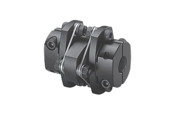
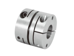
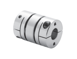
Sakai LCD-B Series Precision Spring Coupling
Manufacturer: Sakai Manufacturing Co., Ltd.
Model: LCD-B Series
Features
- Streamlined body results in low inertia specifications.
- Unique laminated leaf spring with excellent precision and rigidity used as flexure material. Bolting two sets of laminated leaf springs to the hub creates a non-backlash structure and high flexibility, achieving high precision and high torque rotation transmission.
- Two sets of laminated leaf springs sandwiched between spacers absorb eccentricity, angular misalignment, and axial displacement. A precision shaft coupling combines high versatility, high flexibility, easy centering, and high precision rotation transmission.
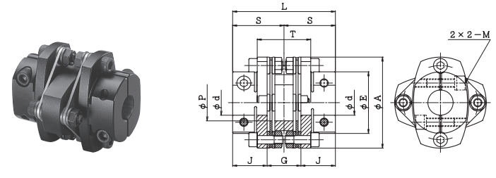
Specifications
(Dimensions: mm)
| Model number | d | A | E | P | L | S | T | J | G | M |
|---|---|---|---|---|---|---|---|---|---|---|
| LCD-45B | 8~16 | 45 | 31 | 18 | 52 | 26 | 28 | 17 | 18 | M4 |
| LCD-55B | 10~19 | 55 | 38 | 21 | 60 | 30 | 32 | 20 | 20 | M5 |
| LCD-65B | 12~ 25 | 65 | 44 | 26 | 73 | 36.5 | 38 | 24.5 | 24 | M6/M5 |
| LCD-80B | 12~35 | 80 | 57 | 36 | 83 | 41.5 | 39 | 29 | 25 | M8/M6 |
| LCD-90B | 17~35 | 90 | 63 | 37 | 96 | 48 | 54 | 31 | 34 | M8 |
| LCD-100B | 20~40 | 100 | 70 | 41 | 109 | 54.5 | 57 | 36 | 37 | M10/M8 |
| LCD-125B | 32~42 | 125 | 88 | 51 | 130 | 65 | 71 | 42.5 | 45 | M12 |
| LCD-155B | 45~60 | 155 | 112 | 61 | 154 | 77 | 84 | 50 | 54 | M14 |
| Model number | Allowable torque N・m | Allowable eccentricity mm | Allowable deviation angle ° | Allowable axial displacement mm | Maximum rotation speed min-1 | Torsional stiffness | Axial spring constant N/mm | Moment of inertia kg・m2 | Mass kg | |
|---|---|---|---|---|---|---|---|---|---|---|
| Overall N・m/rad | Leaf spring only N・m/rad | |||||||||
| LCD-45B | 12 | 0.23 | 1 | ±0.65 | 10,000 | 0.74×10⁴ | 1.25×10⁴ | 29 | 0.51×10⁻⁴ | 0.24 |
| LCD-55B | 25 | 0.27 | 1 | ±0.79 | 10,000 | 1.47×10⁴ | 2.50×10⁴ | 29 | 1.36×10⁻⁴ | 0.43 |
| LCD-65B | 40 | 0.32 | 1 | ±0.93 | 10,000 | 2.94×10⁴ | 1.30×10⁵ | 62 | 3.20×10⁻⁴ | 0.7 |
| LCD-80B | 80 | 0.33 | 1 | ±1.15 | 10,000 | 5.88×10⁴ | 1.02×10⁵ | 37 | 7.79×10⁻⁴ | 1.11 |
| LCD-90B | 180 | 0.45 | 1 | ±1.27 | 10,000 | 8.82×10⁴ | 1.95×10⁵ | 45 | 1.56×10⁻³ | 1.76 |
| LCD-100B | 250 | 0.47 | 1 | ±1.43 | 10,000 | 1.18×10⁵ | 3.30×10⁵ | 53 | 2.65×10⁻³ | 2.46 |
| LCD-125B | 400 | 0.58 | 1 | ±1.79 | 10,000 | 2.06×10⁵ | 6.50×10⁵ | 42 | 8.28×10⁻³ | 5.12 |
| LCD-155B | 800 | 0.7 | 1 | ±2.25 | 10,000 | 3.23×10⁵ | 1.15×10⁵ | 29 | 2.39×10⁻² | 9.28 |
Standard Shaft Hole Diameter: d
(Unit: mm)
| Model number | d | |||||||||||||||||||||
|---|---|---|---|---|---|---|---|---|---|---|---|---|---|---|---|---|---|---|---|---|---|---|
| 8 | 10 | 11 | 12 | 13 | 14 | 15 | 16 | 17 | 18 | 19 | 20 | 22 | 24 | 25 | 28 | 30 | 32 | 35 | 38 | 40 | 42 | |
| LCD-45B | ● | ● | ● | ● | ● | ● | ● | ● | – | – | – | – | – | – | – | – | – | – | – | – | – | – |
| LCD-55B | – | ● | ● | ● | ● | ● | ● | ● | ● | ● | ● | 🟤 | – | 🟤 | – | – | – | – | – | – | – | – |
| LCD-65B | – | – | – | ● | ● | ● | ● | ● | ● | ● | ● | ● | ● | ● | ● | – | – | – | – | – | – | – |
| LCD-80B | – | – | – | ● | ● | ● | ● | ● | ● | ● | ● | ● | ● | ● | ● | ● | ● | ● | ● | – | – | – |
| LCD-90B | – | – | – | – | – | – | – | – | ● | ● | ● | ● | ● | ● | ● | ● | ● | ● | ● | – | – | – |
| LCD-100B | – | – | – | – | – | – | – | – | – | – | – | ● | ● | ● | ● | ● | ● | ● | ● | ● | ● | – |
| LCD-125B | – | – | – | – | – | – | – | – | – | – | – | – | – | – | 🟤 | 🟤 | 🟤 | ● | ● | ● | ● | ● |
| Model number | d | ||||||||
|---|---|---|---|---|---|---|---|---|---|
| 35 | 38 | 40 | 42 | 45 | 48 | 50 | 55 | 60 | |
| LCD-155B | 🟤 | 🟤 | 🟤 | 🟤 | ● | ● | ● | ● | ● |
- The moment of inertia and mass are calculated, the shaft hole diameter is at its maximum.
- Be sure to insert the mounting shaft up to the J dimension.
- The recommended shaft tolerance is h6. (Shaft diameter 35mm, tolerances of 0 to +0.010 are supported.)
- The allowable axial displacement represents the case the deviation angle is zero.
- The maximum rotation speed does not take dynamic balance into consideration.
- The 🟤 mark indicates a non-standard hole diameter (delivery confirmation hole diameter).
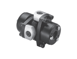
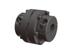
Related Products
REQUEST QUOTATION

PAYMENT

LINK


