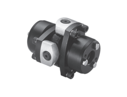
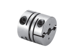
Sakai
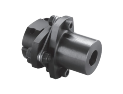
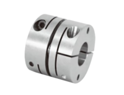
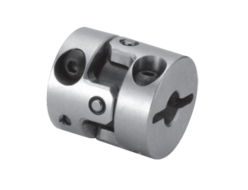
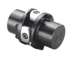
Sakai TCFFD Series Precision Spring Coupling
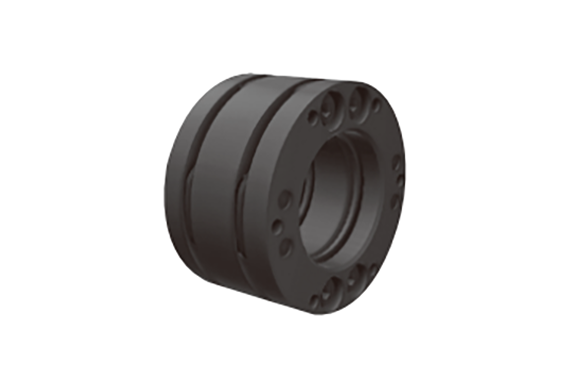
Manufacturer: Sakai Manufacturing Co., Ltd.
Model: TCFFD Series
Feature
- They unitized and launched the plate spring part of the TCD-B series. It is now compatible with a wider range of combinations.
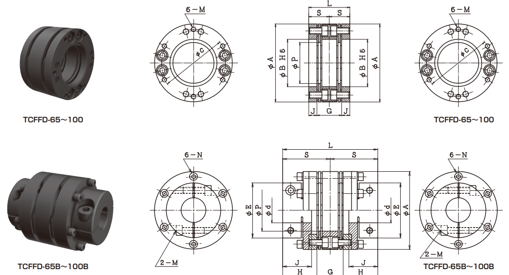
Example Of Use

Specifications
(Dimensions: mm)
| Model | Allowable Torque (N·m) | Allowable Eccentricity (mm) | Allowable Angular Misalignment (°) | Allowable Axial Displacement (mm) | Max Rotational Speed (min⁻¹) | Torsional Stiffness (N·m/rad) | Axial Spring Constant (N/mm) | Moment of Inertia (kg·m²) | Mass (kg) |
|---|---|---|---|---|---|---|---|---|---|
| TCFFD-65 | 80 | 0.2 | 1 | ±0.92 | 10000 | 1.14×10⁵ | 66 | 3.49×10⁻⁴ | 0.5 |
| TCFFD-80 | 140 | 0.23 | 1 | ±1.15 | 10000 | 1.61×10⁵ | 45 | 9.82×10⁻⁴ | 0.91 |
| TCFFD-93 | 250 | 0.3 | 1 | ±1.27 | 10000 | 3.40×10⁵ | 52 | 2.45×10⁻³ | 1.74 |
| TCFFD-100 | 320 | 0.31 | 1 | ±1.41 | 10000 | 5.15×10⁵ | 75 | 3.33×10⁻³ | 2 |
| Model | A | B | C | P | L | S | J | G | M |
|---|---|---|---|---|---|---|---|---|---|
| TCFFD-65 | 65 | 38 | 57 | 36 | 35 | 17.5 | 7 | 21 | M4 |
| TCFFD-80 | 80 | 50 | 70 | 46 | 44 | 22 | 9.5 | 25 | M5 |
| TCFFD-93 | 93 | 54 | 80 | 51 | 56 | 28 | 12 | 32 | M6 |
| TCFFD-100 | 100 | 62 | 85 | 56 | 58 | 29 | 12 | 34 | M6 |
Dimensions
(Unit: mm)
| Model | d | A | E | P | L | S | J | H | G | N | M |
|---|---|---|---|---|---|---|---|---|---|---|---|
| TCFFD-65B | 14~25 | 65 | 48 | 36 | 83 | 41.5 | 28 | 31 | 21 | M4 | M8/M6 |
| TCFFD-80B | 15~35 | 80 | 59 | 46 | 105 | 52.5 | 35.5 | 40 | 25 | M5 | M10/M8 |
| TCFFD-93B | 19~35 | 93 | 66 | 51 | 126 | 63 | 40 | 47 | 32 | M6 | M10 |
| TCFFD-100B | 20~40 | 100 | 71 | 56 | 132 | 66 | 42 | 49 | 34 | M6 | M12/M10 |
- The dimensions of TCFFD-B/K follow those of TCFFD-A.
- The allowable radial direction displacement represents the case eccentricity and tilt angle are zero.
- The eccentricity and tilt angle act simultaneously, the allowable tilt angle has restricted.
- The maximum rotational speed does not consider dynamic balance.
- For bolt clamp hubs, the recommended shaft tolerance is h6.
- For bolt clamp hubs, after pushing the shaft into the designated position, tighten two of the hub’s clamping bolts alternately in 2-3 steps to the specified tightening torque. Tighten the other two clamping bolts on the opposite side in the same manner.
Feature
- They unitized the double plate spring part for high torque transmission. You can combine it with any type of shaft coupling method.
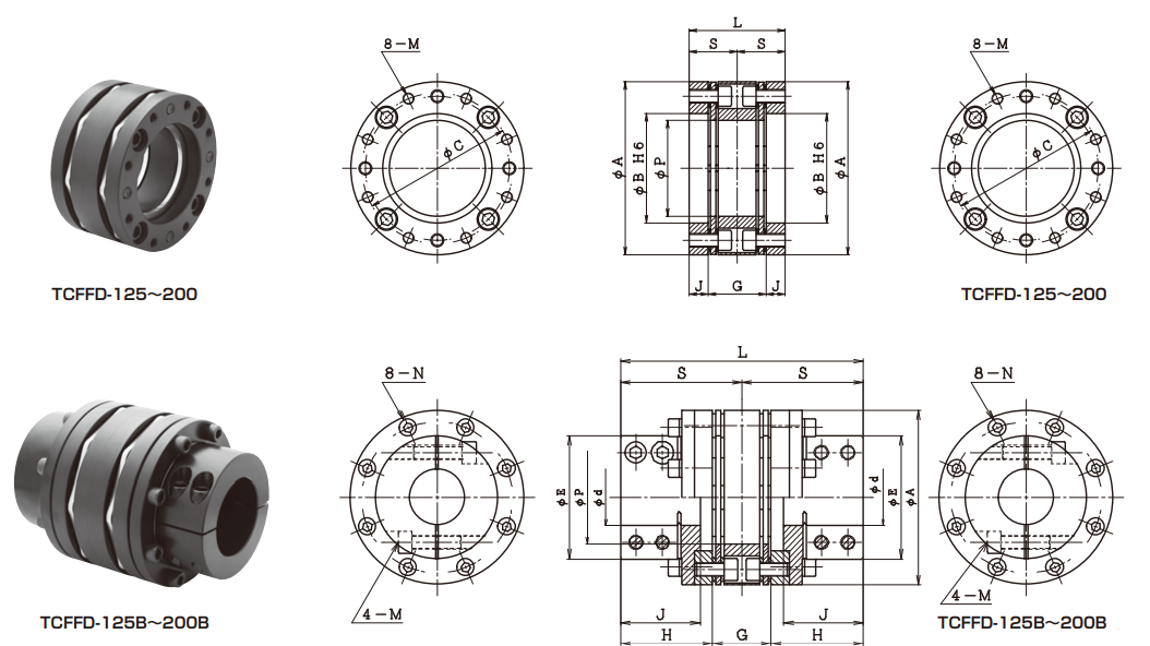
Example Of Use

Specifications
(Dimensions: mm)
| Model | Allowable Torque (N·m) | Allowable Eccentricity (mm) | Allowable Angular Misalignment (°) | Allowable Axial Displacement (mm) | Max Rotational Speed (min⁻¹) | Torsional Stiffness (N·m/rad) | Axial Spring Constant (N/mm) | Moment of Inertia (kg·m²) | Mass (kg) |
|---|---|---|---|---|---|---|---|---|---|
| TCFFD-125 | 800 | 0.59 | 1 | ±1.80 | 10000 | 1.84×10⁶ | 480 | 9.21×10⁻³ | 3.64 |
| TCFFD-155 | 1500 | 0.75 | 1 | ±2.20 | 8000 | 3.28×10⁶ | 550 | 2.77×10⁻² | 7.3 |
| TCFFD-200 | 3200 | 0.87 | 1 | ±2.93 | 8000 | 29.2×10⁶ | 325 | 8.32×10⁻² | 12.14 |
| Model | A | B | C | P | L | S | J | G | M |
|---|---|---|---|---|---|---|---|---|---|
| TCFFD-125 | 125 | 76 | 108 | 66 | 68 | 34 | 13 | 42 | M8 |
| TCFFD-155 | 155 | 98 | 135 | 86 | 86 | 43 | 17 | 52 | M10 |
| TCFFD-200 | 200 | 125 | 176 | 125 | 100 | 50 | 19 | 82 | M12 |
Dimensions
(Unit: mm)
| Model | d | A | E | P | L | S | J | H | G | N | M |
|---|---|---|---|---|---|---|---|---|---|---|---|
| TCFFD-125B | 30~55 | 125 | 88 | 66 | 174 | 87 | 57 | 66 | 42 | M8 | M10 |
| TCFFD-155B | 40~70 | 155 | 115 | 86 | 210 | 105 | 66 | 79 | 52 | M10 | M12 |
| TCFFD-200B | 60~100 | 200 | 153 | 125 | 246 | 123 | 78 | 92 | 62 | M12 | M14 |
- The dimensions of TCFFD-B/K follow those of TCFFD-A.
- The allowable radial direction displacement represents the case eccentricity and tilt angle are zero.
- If eccentricity and tilt angle act simultaneously, the allowable tilt angle has restricted.
- The maximum rotational speed does not consider dynamic balance.
- For bolt clamp hubs, the recommended shaft tolerance is h6.
- For bolt clamp hubs, after pushing the shaft into the designated position, tighten the four clamping bolts on one side alternately in 2-3 steps to the specified tightening torque. Tighten the four clamping bolts on the opposite side in the same manner.

