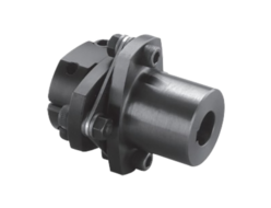
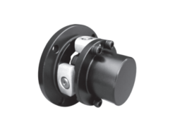
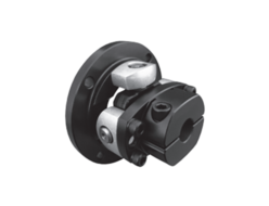
Sakai
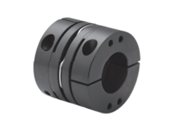
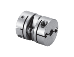
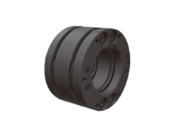
Sakai UCR Series Precision Compensation Coupling
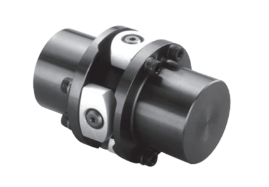
Manufacturer: Sakai Manufacturing Co., Ltd.
Model: UCR Series
Feature
- Adapt the unmachined shaft hole to various mounting specifications. It supports a maximum outer diameter of 200 mm.
Performance
(Dimensions: mm)
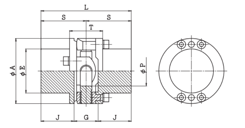
| Model | Allowable Torque (N·m) | Maximum Torque (N·m) | Allowable Thrust Load (N) | Allowable Eccentricity (mm) | Allowable Angular Misalignment (°) | Max Rotational Speed (min⁻¹) | Torsional Stiffness (N·m/rad) | Moment of Inertia (kg·m²) | Mass (kg) |
|---|---|---|---|---|---|---|---|---|---|
| UCR-34 | 2.5 | 5 | 170 | 0.2 | 1 | 6000 | 0.59×10⁴ | 0.15×10⁻⁴ | 0.14 |
| UCR-38 | 5 | 10 | 300 | 0.2 | 1 | 6000 | 0.95×10⁴ | 0.26×10⁻⁴ | 0.2 |
| UCR-45 | 10 | 20 | 500 | 0.2 | 1 | 6000 | 1.91×10⁴ | 0.69×10⁻⁴ | 0.39 |
| UCR-55 | 20 | 40 | 850 | 0.2 | 1 | 6000 | 5.01×10⁴ | 1.95×10⁻³ | 0.73 |
| UCR-65 | 40 | 80 | 1450 | 0.2 | 1 | 6000 | 1.08×10⁵ | 4.19×10⁻³ | 1.12 |
| UCR-80 | 80 | 160 | 2350 | 0.2 | 1 | 6000 | 2.37×10⁵ | 1.21×10⁻³ | 2.16 |
| UCR-100 | 160 | 320 | 3750 | 0.2 | 1 | 6000 | 4.66×10⁵ | 3.67× 10⁻³ | 4.22 |
| UCR-125 | 320 | 640 | 6000 | 0.2 | 1 | 6000 | 8.80×10⁵ | 1.17×10⁻² | 8.29 |
| UCR-155 | 640 | 1280 | 9750 | 0.2 | 1 | 6000 | 1.66×10⁶ | 3.36×10⁻² | 15.46 |
| UCR-200 | 1600 | 3200 | 19300 | 0.2 | 1 | 6000 | 4.90×10⁶ | 1.16×10⁻¹ | 31.49 |
| Model | Maximum Shaft Diameter | A | E | P | L | S | T | J | G |
|---|---|---|---|---|---|---|---|---|---|
| UCR-34 | 11 | 34 | 22 | 12 | 40 | 20 | 18 | 14 | 12 |
| UCR-38 | 14 | 38 | 25 | 15 | 50 | 25 | 20 | 17.5 | 15 |
| UCR-45 | 19 | 45 | 31 | 20 | 64 | 32 | 24 | 23.5 | 17 |
| UCR-55 | 24 | 55 | 38 | 25 | 80 | 40 | 28 | 30 | 20 |
| UCR-65 | 28 | 65 | 44 | 30 | 90 | 45 | 33 | 33 | 24 |
| UCR-80 | 38 | 80 | 57 | 39 | 110 | 55 | 36 | 41 | 28 |
| UCR-100 | 42 | 100 | 68 | 45 | 140 | 70 | 48 | 53 | 34 |
| UCR-125 | 60 | 125 | 88 | 61 | 170 | 85 | 61 | 63 | 44 |
| UCR-155 | 75 | 155 | 112 | 76 | 200 | 100 | 71 | 74.5 | 51 |
| UCR-200 | 90 | 200 | 138 | 92 | 250 | 125 | 108 | 91 | 58 |
- UCR-125, UCR-155, and UCR-200 are standard products.
- Permissible torque indicates the value at a rotational speed of 1500 min⁻¹.
- Maximum torque is the torque momentarily transmitted startup and braking.
- Permissible thrust load represents the static permissible load with zero load torque.
- The torsional rigidity value is for the metal part only.
- It may be possible to use it at an offset or angle greater than the permissible value. Please contact us for more information.
- The permissible torque and maximum torque do not take into account the strength of the drive shaft and key.
- Adapt the UCR-200 to a hub bolt clamping specification as a special specification.
Matetial
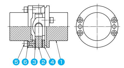
| Part No. | Part Name | Material |
|---|---|---|
| ① | Hub | S45C |
| ② | Cross Pin | SCM420 |
| ③ | Metal | Polyimide Resin |
| ④ | Arm | A2017 |
| ⑤ | Arm Clamping Bolt | SCM435 |
| ⑥ | Spring Washer | SWRH |
※ The metal of UCR-125, UCR-155, and UCR-200 is ordinary cold-rolled steel (SPCE).
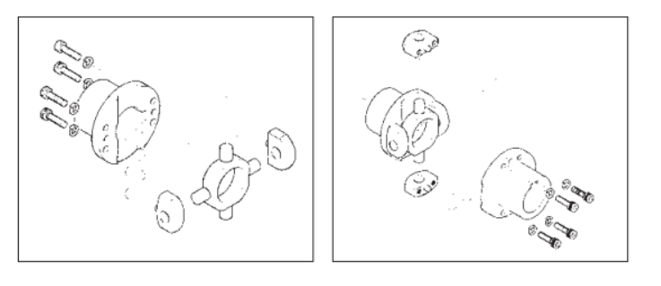
Shaft Installation (In the case of keyway tightening)
- Insert the two hubs onto the respective shafts.
- Fix the two cross pins to the hubs using the arm clamping bolts, securing two bolts to each hub. Use a torque wrench to tighten the bolts according to the tightening torque listed in the table (page 16). Also, apply an anti-seize compound to the bolts.
- For the shaft and keyway tightening, set screws should be installed in the fixed keyway or at two points that are 90° apart from the key’s top, securing with two screws.
