Suntest
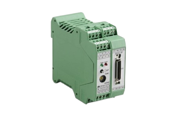
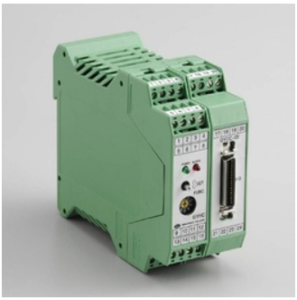
Suntest GYDC-05 Controller
Manufacturer: Suntest Co.,Ltd
Model: GYDC-05
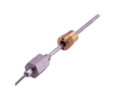
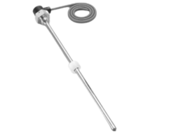
Magnetostrictive Displaiacement Transducer
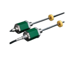
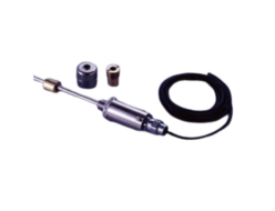
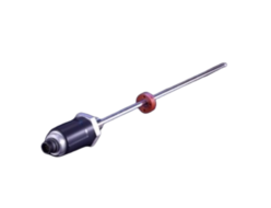
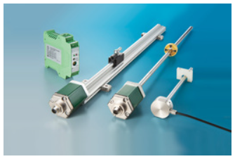 Model GY Series are “Displacement Transducers” employing magnetostrictive phenomena, especially the Wiedemann effect. An ultra-sonic wave is generated by a moving magnet operating near a magnetostrictive wave guide on which the sonic wave propagates up to the head of the transducer.
The propagation time is precisely measured by state of the art technology and then the absolute displacement transducer is operational.
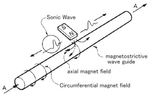
[ Principle ]
The figure shows the fundamental principle of operation.
When a current pulse like A is given to the wave guide, it generates a circumferential magnetic field on the wave guide, then placement of the movable magnet (polarized axially) as shown, only the axial magnetic field of the magnet affecting the wave guide produces a resultant field as indicated by the dotted line.
The vector combination of these two fields produces torsional strain, a phenomenon known as the Wiedemann Effect.
It is a form of vibration and propagates along the wave guide in the form of a transverse ultra-sonic wave.
The GY series displacement transducers detect the propagation time of the ultra-sonic wave.
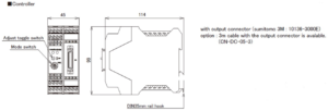
GYDC-05 Controller
High accuracy digital output
(Parallel, SSI, A/B pulse)
GYDC-05 controller enables digital output of 1μm resolution and also analogue output of the position or the velocity (option). With option, SSI output and the incremental output (A/B pulse) are available.
And putting 2 pcs magnets on one probe and detecting each magnet position or relative distance between 2 magnets are possible. It has toggle switches on front face for zero/gain adjustment, mounting with DIN rail. With the captive software (GPM), zero and gain adjustment is possible at user side.
- CE marking
- Noise cancellation
- GPM setting
◆Auto-calibration
In combination with the probe (GYMR6, GYSE-R, GYKMR, GYRHP-MR6) having auto calibration function, a difference in the output when you change the probe is adjusted automatically.
Specifications
| Position (digital) (24bit) | Parallel, Binary code (*1), Negative logic (*2) ( option :SSI or A/B incremental output ) |
|---|---|
| Resolution ( digital ) | Std. 0.01mm ( Min. 0.001mm ) (*3) 0.1mm (*4) |
| Position ( OUT1 ) ( analogue ) | 0〜10V ( Max.5mA, Min.2kΩ ) or 4〜20mA ( load :Max.500Ω) |
| Resolution ( analogue ) | 16bit ( 1/65536 ) (*3) ≦0.01%FS (*4) |
| Velocity ( OUT2 ) | Option ±10V or 4〜20mA |
| Alarm (*5) | Open collector 0.1A 30VDC |
| Power supply | +24VDC±2V ( ≦160mA ) |
| Sampling freq. (*6) | Std. 1kHz ( Total rod length : 1300mm ) |
| Temp. drift | ≦±10ppmFS/°C |
| Operating temp. | 0°C〜+65°C |
| Storage temp. | -20°C〜+75°C |
- The above mentioned accuracy applies to sensors with an effective stroke of 300mm or more.
- The specification of stroke less than 300mm is equal that of stroke 300mm.
(*1)can be changed to Gary code at user side
(*2)Tr On = output “0”
(*3)associated probe : GYMR6, GYSE-R, GYcRS, GYMR5, GYFRS, GYKMR, GYRHP-MR6, EX-GYdT-RS
(*4)associated probe : GYMS, GYGS, GYPM, GYPE2K, GYPMR, GYcRP, GYHTR, GYHR, EX-GYdS-RP, IGY4
(*5)cable disconnection and magnet drop
(*6)Sampling frequency is Max. 3.75kHz. It depends on the total rod length (model⑩), and the consumption current increases.
Model No.

① Digital output
1:Standard, parallel output
2100 :with A/B incremental(pulse freq. :1MHz)
2200 :with A/B incremental(pulse freq. :500kHz)
(standard for resolution D7 or D8)
2300 :with A/B incremental(pulse freq. :250kHz)
(standard for resolution D2-D5)
2400 :with A/B incremental(pulse freq. :125kHz)
2600 :with A/B incremental(pulse freq. :31kHz)
2700 :with A/B incremental(pulse freq.: 15kHz)
005A :with SSI output (26bit)
005S :with SSI output (26bit) : External sync.
- In case of A/B incremental, Max. magnet speed is limited with the selected resolution and pulse freq. For standard setting, the speed is as below.
| Resolution(mm) | Pulse freq. | Max. magnet speed |
|---|---|---|
| 0.1 | 250kHz | (*)15m/sec |
| 0.05 | 250kHz | (*) 15m/sec |
| 0.01 | 250kHz | 8m/sec |
| 0.005 | 250kHz | 4m/sec |
| 0.002 | 500kHz | 3.2m/sec |
| 0.001 | 500kHz | 1.6m/sec |
(*)For the noise cancellation function
- Both SSI output and incremental output (A/B pulse) are available for one unit. In that case, Model code would be 「225A」, for example.
② Resolution
D2 :0.1mm
D3 :0.05mm
D4 :0.01mm
D5 :0.005mm
D7 :0.002mm
D8 :0.001mm
「D4」is std. : GYSE-R, GYcRS, GYMR5, GYMR6, GYKMR, GYRHP-MR6, GYFRS, EX-GYdT-RS
「D2」only : GYGS, GYMS, GYPM, GYPMR, GYcRP, GYHR, GYHTR, EX-GYdS-RP, IGY4, GYPE2K
③ Direction of output
D :output data increase toward probe tip
R :output data decrease toward probe tip
④ Probe
MR6 :GYMR6
SR :GYSE-R
RS :GYcRS
RP :GYcRP
R5 :GYMR5
FS :GYFRS
HTR :GYHTR
HR24 :GYHR
MS :GYMS
GS :GYGS
PM :GYPM
P2 :GYP2K
PR :GYPMR
KMR :GYKMR
PMR6 :GYRHP-MR6
ETS :EX-GYdT-RS
ESP :EX-GYdS-RP
I4 :GY4
⑤ Effective stroke (mm)
⑥ Thread dead zone
□ :□ mm (option) (specified by customers)
⑦ Associated magnet or float
| magnet | float |
|---|---|
| MG0:No.Φ M0SM :No.ΦSPM M0LM :No.ΦLPM M2P:No.2P M2PN:No.2PN M3 :No.3 M11N :No.11N M11 :No.11 T144 :No.T14-M4 T142 :No.T14-M2 T163 :No.T16-M3 T162 :No.T16-M2 BA :No.2KYN-17-LG | F28S :Φ28 SS316L F30S :Φ30 SS316L F40S :Φ40 SS316(B) F42S :Φ42.5 SS316L F50S :Φ50 SS316L F54S :Φ54 SS304 F25N :RF-A10 plastic F28N :RF-A6 plastic |
- Same as the selected magnet or float of probe.
- Please consult our factory in case of requesting special magnet or float.
- This model code means only specifying associated magnet or float.
- Ordering magnet or float individually.
⑧ Position output(OUT1)
AD :0-10V(When magnet moves toward tip, output increase)
AR :10-0V(When magnet moves toward tip, output decrease)
BD :4-20mA(When magnet moves toward tip, output increase)
BR :20-4mA(When magnet moves toward tip, output decrease)
CD□□ :bipolar output(-□V〜+□V)
(for example CD10 :-10V〜+10V)
CR□□ :bipolar output(+□V〜-□V)
(for example CR0 5 :+5V〜-5V)
V Z/F :option (specified voltage)
(for example V1/5 :1〜5V, V9.5/0.5 :9.5〜0.5V)
I Z/F :option (specified current)
(for example I5.2/20 :5.2〜20mA, I18/5 :18〜5mA)
【 Z=output at zero position, F=output at full position 】
⑨ Option : Analogue output(OUT2)
- N :without option (Std.)
- position output :select from ⑧
- velocity output(Note1)
VA[ ] :±10V
WB[ ] :4〜20mA
[ ]:max velocity (1.00-999mm/sec)
(ex.9R99: max velocity=9.99mm/sec)
(Note1)
VA :When magnet stops, output is 0V.
When moving toward probe tip, +10V.
WB :When magnet stops, output is 4mA.
When moving in any direction, 20mA
⑩ Option
2ME:2 magnets, each magnet position (analog output)(*)
2MR:2 magnets, relative distance between 2pcs(OUT1 only, analogue out put )
X2 :2kHz sampling (total rod length : Max. 700mm)
X3 :3kHz sampling (total rod length : Max. 500mm)
X4 :3.75kHz sampling (total rod length : Max. 400mm)
P :PNP (Parallel output)
HS :resin coating against humidity
(*) 2 magnets option
- Min. proximity distance between magnets is 75mm. (Min. proximity distance between magnets varies depending on the magnet type.)
- When using other magnets, please consult our factory.
【Auto calibration function】
♦In combination with the probe (GYMR6, GYSE-R, GYKMR, GYRHP-MR6) having auto calibration function, a difference in the output when you change the probe is adjusted automatically.
Dimensions
Wiring
| Pin number | Function |
|---|---|
| 1 | |
| 2 | |
| 3 | |
| 4 | |
| 5 | |
| 6 | |
| 7 | |
| 8 |
Connection for probe, Please refer to each manual
| Pin number | Function |
|---|---|
| 9 | OUT1(+) |
| 10 | OUT1(−) |
| 11 | OUT2(+) |
| 12 | OUT2(−) |
| 13 | Power(+) |
| 14 | Power(−) |
| 15 | Alarm(+) |
| 16 | Alarm(−) |
| Pin number | Function |
|---|---|
| 17 | DATA(+) |
| 18 | DATA(−) |
| 19 | CLK(+) |
| 20 | CLK(−) |
| 21 | A pulse(+) |
| 22 | A pulse(−) |
| 23 | B pulse(+) |
| 24 | B pulse(−) |
Parallel output connection
| Number | Function |
|---|---|
| 35 | EXT |
| 33 | FULL |
| 31 | HOLD |
| 29 | COM |
| 27 | RDY |
| 25 | STB |
| 23 | D22 |
| 21 | D20 |
| 19 | D18 |
| Number | Function |
|---|---|
| 36 | EXT2 |
| 34 | INC |
| 32 | ZERO |
| 30 | COM |
| 28 | LE |
| 26 | ERR |
| 24 | D23 |
| 22 | D21 |
| 20 | D19 |
| Number | Function |
|---|---|
| 17 | D16 |
| 15 | D14 |
| 13 | D12 |
| 11 | D10 |
| 9 | D8 |
| 7 | D6 |
| 5 | D4 |
| 3 | D2 |
| 1 | D0 |
| Number | Function |
|---|---|
| 18 | D17 |
| 16 | D15 |
| 14 | D13 |
| 12 | D11 |
| 10 | D9 |
| 8 | D7 |
| 6 | D5 |
| 4 | D3 |
| 2 | D1 |
*When using parallel output, and incremental output, and SSI output, supplying 24VDC at PIN 36 (EXT2) and 0V at PIN 29 (COM) is necessary. (consumption 150mA)

REQUEST QUOTATION

PAYMENT

LINK


