Suntest
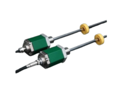
Suntest GYKMR Probe
Manufacturer: Suntest Co.,Ltd
Model:
Magnetostrictive Displaiacement Transducer
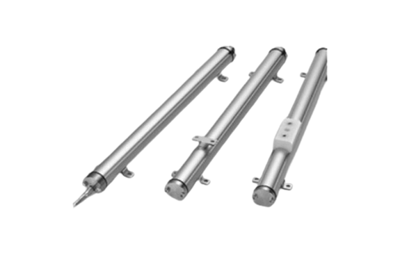
 Model GY Series are “Displacement Transducers” employing magnetostrictive phenomena, especially the Wiedemann effect. An ultra-sonic wave is generated by a moving magnet operating near a magnetostrictive wave guide on which the sonic wave propagates up to the head of the transducer.
The propagation time is precisely measured by state of the art technology and then the absolute displacement transducer is operational.
[ Principle ]
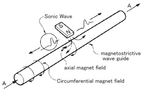
The figure shows the fundamental principle of operation.
When a current pulse like A is given to the wave guide, it generates a circumferential magnetic field on the wave guide, then placement of the movable magnet (polarized axially) as shown, only the axial magnetic field of the magnet affecting the wave guide produces a resultant field as indicated by the dotted line.
The vector combination of these two fields produces torsional strain, a phenomenon known as the Wiedemann Effect.
It is a form of vibration and propagates along the wave guide in the form of a transverse ultra-sonic wave.
The GY series displacement transducers detect the propagation time of the ultra-sonic wave.
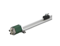
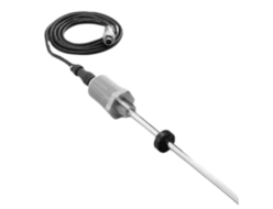
GYKMR Probe
High accuracy with external controller
GYKMR is replacement model of GYKM-RS which head part became slim. And it was added auto calibrationfunction. By the function, a difference in the output when you change the probe is adjusted automatically.
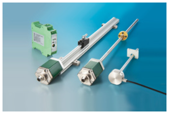
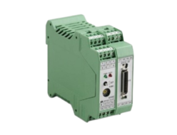
◆Associated controller
- Analogue output : GYHC
- Digital output : GYDC-S1, GYDC-05
- IRDS-GY (page 109) : When using the IRDM, you can connect with CC-Link, CC-Link IE Field, PROFIBUS, EtherNet/IP, and EtherCAT.
- DC-Q (page 108) : MELSEC-Q built-in unit
Specifications
| Non-linearity | ≦±0.025%FS Typ. |
|---|---|
| Resolution | (Analogue) 16bit (Digital) Min. 1μm |
| Repeatability | ≦±0.01%FS |
| Temp. drift | ≦±20ppmFS/°C |
| Operating temp. | 0°C〜+65°C |
| Storage temp. | -20°C〜+65°C |
| Vibration | 3G ( or 40Hz 2mmPP ) |
| Shock | 10G ( 2msec ) |
| IP grade | IP53, IP64, IP65 |
- The above mentioned accuracy applies to sensors with an effective stroke of 300mm or more.
- The specification of stroke less than 300mm is equal that of stroke 300mm.
- Resolution depends on associated controller.
- Mounting brackets (fixing clamps) are supplied.
- stroke< 600mm : 4 pcs (2 pcs)
- 600〜1000mm : 6 pcs (3 pcs)
- 1001〜1500mm : 8 pcs (4 pcs)
- 1501〜2000mm :10 pcs (5 pcs)
- 2001〜2500mm :12pcs (6 pcs)
Model No.

① Effective stroke
15mm〜2000mm (rod type, T, TW, U)
15mm〜500mm (both end universal joint types)
15mm〜2500mm (TS)
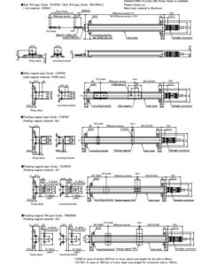
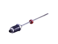
② Magnet
R: rod Φ6 (M5 thread)(Standard)
R2: rod Φ6 (M5 thread)
R88: rod Φ8 (M8 thread)
R85: rod Φ8 (M5 thread)
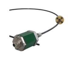
RW88: Both end universal joint type (rod Φ8)<IP64>
U: Slide magnet
T: Floating magnet (gap 1mm)
TS: Floating magnet (gap 4mm)
TW: Floating magnet (gap 8mm)
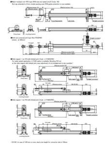
U-FX65 :Slide magnet + rod Φ6 (M5 thread) with linkball joint
U-FX88 :Slide magnet + rod Φ8 (M8 thread) with linkball joint
③ Cable connection
8P : connector type (M12-8pin)
△G□F: pigtail / cable end : free
△G□A: pigtail / cable end : with connector for relay
(□: cable length (m)、Max.10m)(*)
(△: cable type S:standard, H:high temp. cable, R:robot cable, UL : cUL cable)
(*)In case of using extension cable, sensor cable (m) + extension cable (m) ≦ 200m
- Please confirm extension cable on page 120〜122.
④ Output
00 :depends on external controller
⑤ Dead zone
In case of an effective stroke 2001mm or more for floating magnet TS, dead zone length for tip side is 80mm (Std. length 65mm + 15mm). Model code of dead zone will be the actual length (mm).
- S/S : Std.
- S/80 : 2001mm〜(TS type)
⑥ Clamp
K38 : with mounting brackets
F50 : with fixing clamps
N : without mounting brackets and fixing clamps
- The number of pieces included is determined by the stroke. If you need more than that, please specify separately.
- Please refer to page 118 for clamp drawings.
Dimensions
Dimensions
Option
Cable
| Wire color | Pin number | Function |
|---|---|---|
| red | 1 | Sensor power |
| white | 2 | 0V |
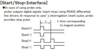
| blue | 3 | Start(−) |
| green | 4 | Start(+) |
| brown | 5 | Stop(−) |
| black | 6 | Stop(+) |
| yellow | 7 | N.C. |
| shield | 8 | shield |
REQUEST QUOTATION

PAYMENT

LINK


