| Module series | Memory block | Input byte | Output byte |
|---|---|---|---|
| IRDS-SV | 8 | 40 | 24 |
Suntest
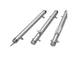
Suntest IRDS-SV. Servo Controller Module
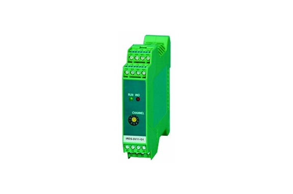
Manufacturer: Suntest Co.,Ltd
Model: IRDS-SV
This is a slave module for the servo controller (Simple Adaptive Control) for hydraulic or pneumatic of IRD series.
High accuracy position or load control for hydraulic or pneumatic cylinder can be built up easily.
[Functions and Features]
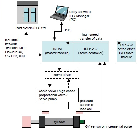
- The data is transferred to the industrial network through IRD master module. (CC-Link, EtherNet/IP, PROFIBUS)
- Adopting Simple Adaptive Control (SAC) theory among other modern control theories, achieved robust control compensating automatically parameter change and time-variant influence in the plant.
- Servo calculation is 200μs with inside DSP and it is independent of cycle time of host system.
- Possible to connect GY sensor directly as position feedback and build up high performance position control system with 1μm resolution. And also possible to connect incremental pulse encoder and build up position control system with the encoder’s resolution.
- IRDS-SV is equipped with 2 ports for analogue input and it is possible to apply to load control with one load cell or two pressure sensors.
- Automatic transfer function : it can acquire feedback signal of various sensor from other IRDS slave module directly. And synchronization servo control to other IRDS-SV module is possible.
- Having two axes inside, possible to switch position (GY sensor or incremental pulse) to pressure (load) (analogue) control in operation.
- IRDS-SV is equipped with motion program function.
- Alarm : upper and lower limit of sensor, alarm of servo deviation and oscillation
- Self diagnosis function : internal IC error, cable error, sensor data error.
- RoHS compliant
Model
IRDS (1) – SV (2) (3) – (4) (5) – (6)
(1) series
IRDS : IRD slave module
(2) module function
SV : servo controller
(3) analogue input / output
| 11 | : voltage input (±10V) / voltage output (±10V) |
| 12 | : voltage input (±10V) / current output (±50mA) |
| 21 | : current input (0~20mA) / voltage output (±10V) |
| 22 | : current input (0~20mA) / current output (±50mA) |
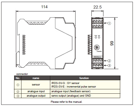
(4) (5) direct connect sensor
| G1 | : GYcRS / GYFRS |
| G2 | : GYcRP |
| G3 | : GYHR |
| G4 | : GYSE-R |
| E1 | : incremental pulse (line driver) |
| E2 | : incremental pulse (open collector) |
(6) special specifications
| blank | : standard |
| 01 | : current output ±100mA |
| others | : customer’s special option |
Occupied memory block and input / output bytes
Specifications
| Items | IRDS-SV□1-G | IRDS-SV□2-G | IRDS-SV□1-E | IRDS-SV□2-E | |||||
|---|---|---|---|---|---|---|---|---|---|
| Servo function | number of control axis | one axis (two axes internally) | |||||||
| servo calculation cycle | 0.2ms | ||||||||
| output signal* | voltage (±10V) | current (±50mA) | voltage (±10V) | current (±50mA) | |||||
| resolution of output | -30000~30000 (for full scale) | ||||||||
| Sensor connect function | number of sensor | one | |||||||
| connect sensor | GY sensor | incremental pulse | |||||||
| suitable sensor | G1: GYcRS / GYFRS G2: GYcRP G3: GYHR G4: GYSE-R | E1: 90°phase difference A/B/Z pulse (multiply by 4) line driver E2: 90°pahse difference A/B/Z pulse (multiply by 4) 24V open collector | |||||||
| position detection method | absolute type | incremental type | |||||||
| max. resolution | G1, G4: 1μm G2, G3: 50μm | depending on the connected sensor | |||||||
| max. cable length | G1, G2, G4: 200m G3: 50m | depending on the connected sensor | |||||||
| sampling frequency | depending on stroke of GY sensor ~300mm: 2kHz, ~1000mm: 1kHz, ~2400mm: 500Hz ~5000mm: 250Hz, ~7500mm: 150Hz | 4M counts (1MHz pulse frequency) | |||||||
| counter size | signed integer 32bit (-2,147,483,648~2,147,483,647) | ||||||||
| Analogue input function | input signal | IRDS-SV11-G voltage (±10V) | IRDS-SV21-G current (±20mA) | IRDS-SV12-G voltage (±10V) | IRDS-SV22-G current (±20mA) | IRDS-SV11-E voltage (±10V) | IRDS-SV21-E current (±20mA) | IRDS-SV12-E voltage (±10V) | IRDS-SV22-E current (±20mA) |
| max. rating input | ±10.5V | ±21mA | ±10.5V | ±21mA | ±10.5V | ±21mA | ±10.5V | ±21mA | |
| number of input | 2 channels | ||||||||
| resolution of input | -30000~30000 (for full scale) | ||||||||
| input updating cycle | 0.2ms | ||||||||
| Isolation | specification | The inside circuit is isolated from power supply by Digital Isolator. Withstand voltage 500VAC for one minute | The inside circuit is isolated from power supply by Digital Isolator. The analogue servo output isn’t isolated from the analogue input. The analogue servo output isn’t isolated from the other terminals. | ||||||
| Power supply | rating | DC24V (±10%) 180mA supplied from IRDM (master module) | |||||||
※servo output voltage (±10V) : load resistance : more than 1kΩ
※servo output current (±50mA) : load resistance : 80Ω Max @ 50mA / 100Ω Max @ 40mA / 150Ω Max @ 30mA / 200Ω Max @ 20mA / 30Ω Max @ 100mA(in case of 100mA output option)
Dimensions
System configuration
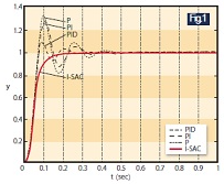
The performance of Simple Adaptive Control (SAC)
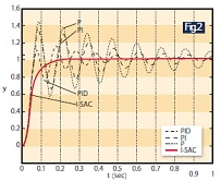
Controlled performance Fig.1 shows an example of a step response of PID and I-SAC servo controller in case of setting target value to one in a typical cylinder positioning control system. While any PID control has an overshoot and reaching the target in an oscillating mode, I-SAC is realizing a smooth and fast response without any oscillations due to its proprietary high-gain feedback. As to the steady-state error, I-SAC can make it totally zero because of its integration compensation feature.
Robustness against variance of circumstances Fig.2 shows that we gave a three times larger mass than in Fig.1 to the cylinder while maintaining same parameters for the controllers. As you can see from the figure, the response is unacceptably oscillatory in case of PID control, which requires re-adjustment of controller parameters by plant engineers. On the other hand, I-SAC provides an excellent robust performance due to its adaptive control structure.
You can check demonstration video of “switching position and load control of pneumatic cylinder” and “the performance comparison of the difference between PID and I-SAC” on our homepage.

REQUEST QUOTATION

PAYMENT

LINK


