Toyo Keiki
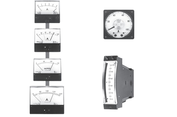
TOYO KEIKI MP Series Contactless Meter Relay
Product Made In Japan
Manufacturer: Toyo Keiki
Model: MP Series
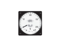
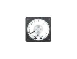
A precise meter relay that uses the deflection of the pointer to control the external circuits.
Toyo Keiki manufactures devices with photoelectric-type configurations.
Features of Meter Relay
- These meter relays possess the various features of a contactless solid state relay.
- The relay circuits and detection relay are integrated into the main body of the meter.
This reduces labor, potential misconnection and other issues in steps such as connection and installation of the included cells. - Highly reliable operation.
- Reliable operation even during minute meter input.
- Set point passage-type relay.
Operating Principles of Photoelectric Type
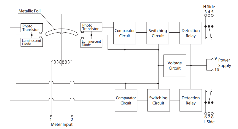
A light source and a receiver are installed on the upper limit and lower limit pointers respectively. The collector current of the photo transistor receiver changes when the foil attached to the movable pointer goes between the light source and the receiver by means of the movable coil input. This change in current is converted to a change in voltage which passes through a comparator circuit and a switching circuit to operate the detection relay.
Square/Edgewise Meter Relay
Photoelectric-type Circuit Configuration
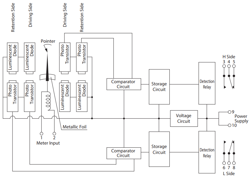
Wide-angle Meter Relay
Photoelectric-type Circuit Configuration
Operation Mechanism of Contactless Meter Relay
While the standard output signal format of the meter relays is a passing signal retaining type, the following three types are used for the MPV-11.
| Output Signal Format | Compatible Meter Relay Format |
|---|---|
| 1. Passing Signal Retaining Type | Wide angle shape, square shape, edgewise shape (MPV type, MPC type, MPE type) |
| 2. Passage Type/Instantaneous Type | Wide Angle Shape (MPV type) |
| 3. Stop Type | Wide Angle Shape (MPV type) |
1. Passing Signal Retaining Type
When the pointer moves past the setting value, the passing signal is retained after signal output. The signal returns to normal after the pointer moves back to the setting value.

2. Passage Type/Instantaneous Type
The same structure as the stop type below, except without the stopper. The output signal returns to normal when the pointer reaches around 8% of the scale length past the setting value.

Precautions for Use
(1) When using a meter relay with L settings (except the wide angle passing signal retaining type), take care not to turn on the power of the meter relay and the meter input at the same time, as the L side signal will be generated continuously until the meter pointer passes the set L pointer.
(2) Avoid using in areas where the meter will be directly exposed to sunlight in the middle of summer, as these are photoelectric-type meter relays.
Wide-angle Meter Relay (Passing Signal Retaining Type)
While 90° displacement meter relays have a shielding plate at the 90° point and can retain the signal by themselves after the pointer passes this, wide-angle meter relays are mechanically unable to do this because the displacement angle (240°) is too large. An electronic storage method is used instead.
As a result, the following issues occur the first time the auxiliary power supply is turned on. Please take this into account when designing circuits.
(1) When the Auxiliary Power Supply is Turned On (L Side Only)
Load relay operation on the L side should be turned on when the meter pointer is a zero and the auxiliary power supply is turned on, but in this case operation does not occur unless the pointer is displaced to around 17mm before the L setting value.
However, this only occurs the first time the pointer passes after turning on the power. After this, operation is turned off when the L setting value is passed and on after returning to normal, and remains on after returning to zero.
This only occurs for the L setting. Normal operation occurs from the start for the H setting.
(2) When the Auxiliary Power Supply is Stopped
If the indicator input and auxiliary power supply of the meter are applied by different circuits, the auxiliary power supply stops when the pointer goes above the H setting value and the H load relay activates. If the pointer continues to indicate the same value, the H load relay returns (turns off) at the same time as the power supply, and usually turns back on when the power is turned on again.
However, if the power is off for 40 seconds or longer, the storage circuit no longer retains the signal, with the result that the previous signal is no longer output when the power is turned on again. If the power is off for 40 seconds or longer, be sure to return the pointer to the zero position by opening or shorting the meter input circuit.
No issue occurs when the power is off for short periods of less than 40 seconds, as the storage circuit remains live.
Standard Specifications
| Model Name | MPC-6 | MPC-8 | MPC-10 | MPC-12 | MPE-150 | MPV-11 | |
|---|---|---|---|---|---|---|---|
| Item | Operating Principles Photoelectric Type | ||||||
| Outside (mm) | 65×60 | 87×80 | 100×83 | 120x 100 | 150×40 | 110 x 110 | |
| Scale Length (mm) | Approx. 48 | Approx. 68 | Approx. 80 | Approx. 100 | Approx. 100 | Approx. 170 | |
| Accuracy Class | 2.5 | 1.5 (2.5) () indicates rectifier type | |||||
| Pointer | Wand Type | Triangular Spearhead Type | Triangular Type | ||||
| Set Pointer | Wand Type H : Red L : Yellow | Spearhead Type H : Red L : Yellow | |||||
| Scale Plate | White Base | ||||||
| Scale Division | 12-25 | 12-25 | 20-45 | 24-50 | 35-75 | ||
| Mounting Posture | Vertical | ||||||
| Cover | Special Anti-electric Resin | Methacrylic Resin and ABS Resin | Methacrylic Resin | ||||
| Base | Between Terminals: Phenol Resin Body :ABS Resin | ABS Resin and Aluminum Board | Between Terminals: Phenol Resin Body : ABS Resin | ||||
| Cover Coating Color | Black or Munsell Notation 7.5B G4/1.5 (Blue-green) | ||||||
| Setting | Both H and L can be set as desired throughout the entire scale range | ||||||
| Minimum Set Gap between H and L (Against Scale Length) | 5% | ||||||
| Operating Error for Setting Value (Against Scale Length) | 2.5 | 1.5 | |||||
| Dead Band | 1.0 | ||||||
| Meter Action | Passage Type | O | o | O | O | O | O |
| Stop Type | — | — | — | — | — | O | |
| Auxiliary Power Supply | DC AC | According to Auxiliary Power Supply Specifications of Meter Relay | |||||
| Output Signal | Retaining Type | O | o | o | o | O | O |
| Instantaneous Type | — | — | — | — | — | O | |
| Contact Arrangement and Capacity | 1A each for H and L AC100V1A | lab each for H and L, AC 100V 1A (resistance load) | Tab each for H and L AC 220V 3A | ||||
| Insulation Test | Between electrical circuit and outer casing of meter: 10MQ or more for 500V mega | ||||||
| Voltage Test | Between electrical circuit and outer casing of meter: AC 1500V (50/60Hz per minute), between contact relay circuit and other electrical circuits: AC 500V (50/60Hz per minute) | ||||||
| Characteristics of Meter | Characteristics of the meter part are based on JIS C standards 1102-1 to 9. | ||||||
| Weight | Approx. 260g | Approx. 380g | Approx. 400g | Approx. 680g | Approx. 560g | Approx 1.4kg | |
| Remarks | With Terminal Cover | With Terminal Cover | With Terminal Cover | With Terminal Cover | With Terminal Cover | With Terminal Cover | |

