- Home
- Products
- Toyo Keiki UVF-11M UuVF-11M Power Factor Meter Electronic Device Type Phase Discrimination Method
Toyo Keiki
Toyo Keiki UVF-11M UuVF-11M Power Factor Meter Electronic Device Type Phase Discrimination Method
Product Made In Japan
Manufacturer: Toyo Keiki
Model: UVF-11M UuVF-11M
Remarks
Using VT, CT
Use a combination of the 110V5A rating meter with VT and CT if the rating on the left is exceeded.
Usable Voltage Range
Rated voltage within ±15% For Small Current
When circuit voltage is rated under 20% (5A rating: less than 1A), it may not be possible to obtain a normal indicator. (Indicates a single scale if the power is off)
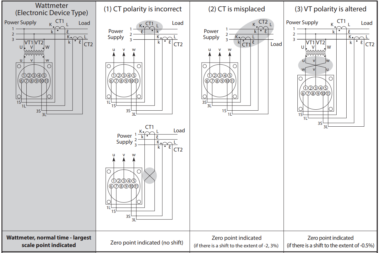
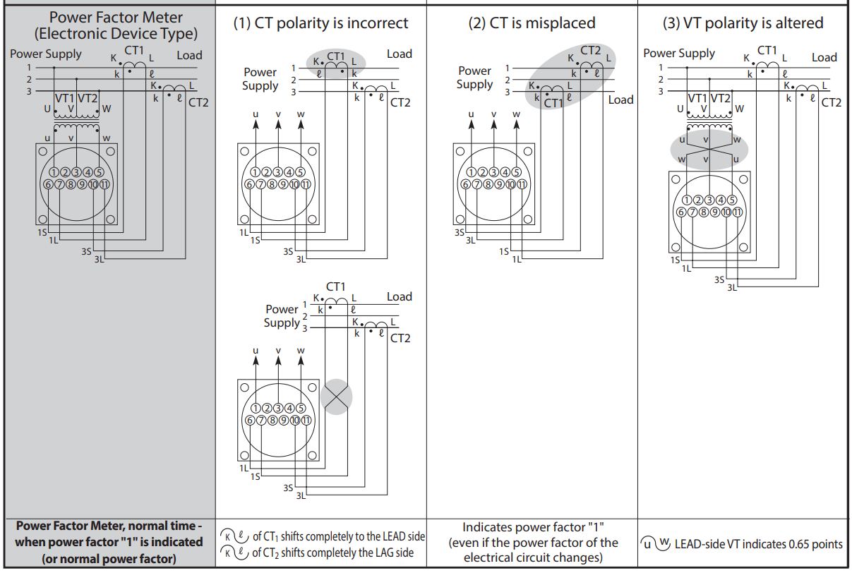
Meter Wiring
1. A normal indicator cannot be obtained if the polarity is reversed. Therefore, be sure to check the phase sequence of the bus and the polarity of VT and CT.
2. For phenomena related to miswiring., Please contact us
Specification
| Product Name | Model Name | Scale | Rating | VA Consumption | Weight | Note | |
|---|---|---|---|---|---|---|---|
| Voltage Circuit | Current Circuit | ||||||
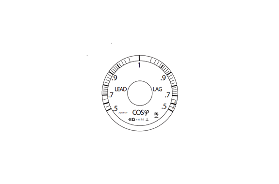
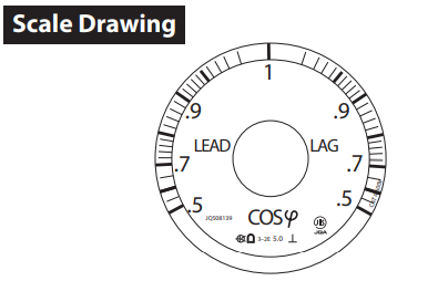
| 1P Power Factor Meter | UVF-11M | LEAD LAG 0.5-1-0.5 COScp | 110V5A 220 V5A | 0.8 V A 1.3VA | 0.8 V A 0.8 V A | Approx. 0.8kg | 50/60HZ Common Use |
| 3P Balanced Power Rate Meter | |||||||
| 3P Unbalanced Power Factor Meter | UuVF-11M | 0.5 V A per phase 1 V A per phase | 0.8 V A per phase 0.8 V A per phase | 50 or 60Hz Required Designation | |||
| 3P4W Power Factor Meter | |||||||
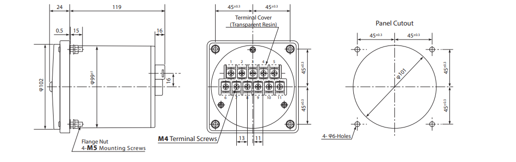
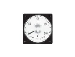
Outside Dimensions
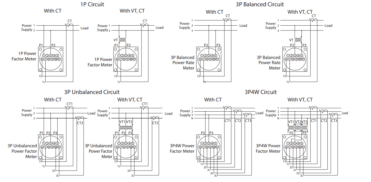
Connection Diagram
Standard Table of Wattmeter Measurement Range
This standards chart is a resource for determining the measurement range values of wattmeters and varmeters, so 3P wattmeter standards are indicated.
| Line Voltage | 110V | 220 V | 440 V | 3300 V | 6600 V | ||||||||||
| VT Ratio | 440V/110V | 3300 V/110 V | 6600 V/110 V | ||||||||||||
| Meter Intrinsic Watts/ Value CT Ratio | 625 Or 667 W | 750 Or 833 W | 1 kW | 1.25 Or 1.33 kW | 1.5 Or 1.67 kW | 2 kW | 625 Or 667 W | 750 Or 833 W | 1 kW | 667 W | 833 W | 1 kW Or 1.11 kW | 625 Or 667 W | 833 W | 1 kW Or 1.11 kW |
| 5A/5A | — | 750 W | 1 kW | 1.2 kW | 1.5 MW | 2 kW | 2.5 kW | 3 kW | 4 kW | 20 kW | 25 kW | 30 kW | 40 kW | 50 kW | 60 kW |
| 7.5 A/5 A | 1 kW | 1.2 kW | 1.5 kW | 2 kW | 2.5 MW | 3 kW | 4 kW | 5 kW | 6 kW | 30 kW | 40 kW | 50 kW | 60 kW | 75 kW | 100 kW |
| 10A/5 A | 1.2 kW | 1.5 kW | 2 kW | 2.5 kW | 3 kW | 4 kW | 5 kW | 6 kW | 8 kW | 40 kW | 50 kW | 60 KW | 80 kW | 100 kW | 120 kW |
| 15 A/5 A | 2 kW | 2.5 kW | 3 kW | 4 kW | 5 kW | 6 kW | 8 kW | 10 kW | 12 kW | 60 kW | 75 kW | 100 kW | 120 kW | 150 kW | 200 kW |
| 20 A/5 A | 2.5 kW | 3 kW | 4 kW | 5 kW | 6 kW | 8 kW | 10 kW | 12 kW | (16kW) | 80 kW | 100 kW | 120 kW | 150 kW | 200 kW | (240 kW) |
| 30 A/5 A | 4 kW | 5 kW | 6 kW | 8 kW | 10 kW | 12 kW | 15 kW | 20 kW | (24 kW) | 120 kW | 150 kW | 200 kW | (240 kW) | 300 kW | 400 kW |
| 40 A/5 A | 5 kW | 6 kW | 8 KW | 10 kW | 12 kW | (16 kW) | 20 kW | (24 kW) | (32 kW) | (160 kW) | 200 kW | (240 kW) | 300 kW | 400 kW | (480 kW) |
| 50 A/5 A | — | 7.5 kW | 10 kW | 12 kW | 15 kW | 20 kW | 25 kW | 30 kW | 40 kW | 200 kW | 250 kW | 300 kW | 400 kW | 500 kW | 600 kW |
| 75 A/5 A | 10 kW | 12 kW | 15 kW | 20 kW | 25 kW | 30 kW | 40 kW | 50 kW | 60 kW | 300 kW | 400 kW | 500 kW | 600 kW | 750 kW | 1 MW |
| 100 A/5 A | 12 kW | 15 kW | 20 kW | 25 kW | 30 kW | 40 kW | 50 kW | 60 kW | 80 kW | 400 kW | 500 kW | 600 kW | 800 kW | 1 MW | 1.2 MW |
| 150 A/5 A | 20 kW | 25 kW | 30 kW | 40 kW | 50 kW | 60 kW | 80 kW | 100 kW | 120 kW | 600 kW | 750 kW | 1 MW | 1.2 MW | 1.5 MW | 2 MW |
| 200 A/5 A | 25 kW | 30 kW | 40 kW | 50 kW | 60 kW | 80 kW | 100 kW | 120 kW | (160 kW) | 800 kW | 1 MW | 1.2 MW | 1.5 MW | 2 MW | (2.4 MW) |
| 300 A/5 A | 40 kW | 50 kW | 60 kW | 80 kW | 100 kW | 120kW | 150 kW | 200 kW | (240 kW) | 1.2 MW | 1.5 MW | 2 MW | (2.4 MW) | 3 MW | 4 MW |
| 400 A/5 A | 50 kW | 60 kW | 80 kW | 100 kW | 120 kW | (160 kW) | 200 kW | (240 kW) | (320 kW) | (1.6MW) | 2 MW | (2.4 MW) | 3 MW | 4 MW | (4.8 MW) |
| 500 A/5 A | — | 75 kW | 100 kW | 120 kW | 150 kW | 200 kW | 250 kW | 300 kW | 400 kW | 2 MW | 2.5 MW | 3 MW | 4 MW | 5 MW | 6 MW |
| 750 A/5 A | 100 kW | 120 kW | 150 kW | 200 kW | 250 kW | 300 kW | 400 kW | 500 kW | 600 kW | 3 MW | 4 MW | 5 MW | 6 MW | 7.5 MW | 10 MW |
| 1000 A/5 A | 120 kW | 150 kW | 200 kW | 250 kW | 300 kW | 400 kW | 500 kW | 600 kW | 800 kW | 4 MW | 5 MW | 6 MW | 8 MW | 10 MW | 12 MW |
| 1500 A/5 A | 200 kW | 250 kW | 300 kW | 400 kW | 500 kW | 600 kW | 800 kW | 1 MW | 1.2 MW | 6 MW | 7.5 MW | 10MW | 12 MW | 15 MW | 20 MW |
| 2000 A/5 A | 250 kW | 300 kW | 400 kW | 500 kW | 600kW | 800 kW | 1 MW | 1.2 MW | (1.6 MW) | 8 MW | 10 MW | 12 MW | 15 MW | 20 MW | (24 MW) |
| 3000 A/5 A | 400 kW | 500 kW | 600 kW | 800 kW | 1 MW | 1.2 MW | 1.5 MW | 2 MW | (2.4 MW) | 12 MW | 15 MW | 20 MW | (24 MW) | 30 MW | 40 MW |
Note) Numerical values inside parentheses indicate values that deviate from JIS standards, but can be manufactured.
Using the Above Chart
[1] For 3P wattmeters, 3P4W wattmeters, and 1P3W wattmeters, the measurement range upper limit values are displayed in the voltage ratios (VT ratio differences) and CT ratio differences in the table above. (There are three types defined for the same VT and CT ratios. Choose the appropriate type.)
(E.g.) For a VT: 3300V/110V, CT: 100A/5A 3P wattmeter… select the appropriate one from 400kW, 500kW or 600kW from the table above.
[2] For 1P wattmeters, 3P varmeters, and 3P4W varmeters, the values displayed above are multiplied by 1/2, and are multiplied by 1/4 for 1P varmeters
Note 1) For varmeters, read kW units as kvar.
Scale is LEAD ~0~LAG kvar.
Example: For a VT: 3300V/110V, CT: 100A/5A 3P varmeter … LEAD250~0~LAG250kvar or LEAD300~0~LAG300kvar (500 × 1/2) (500 × 1/2) (600 × 1/2) (600 × 1/2)
2) For 3P varmeters or 3P4W varmeters with zero left meters, follow the values as displayed above, and for 1P varmeters with zero left meters, the values in the table above are multiplied by 1/2.
[3] If the CT ratio exceeds the range listed above, (for example, VT: 3300V/110V, CT: 5000A/5A 3P wattmeter) select a value from the CT: 500A/5A row (2 MW, 2.5 MW, 3 MW) and multiply it by 10.
Note) In the situation above, scale indicators are 20MW, 25MW and 30MW. (The highest 3 digits of scale should be displayed)
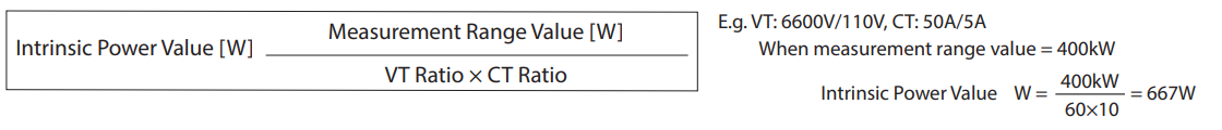
[4] If CT ratios do not correspond with those indicated above (for example, CT: 60A/5A), use the calculation chart below to acquire the measurement range, then choose from among them the value with the best ending number.
Measurement Range Value = Intrinsic Power × VT Ratio × CT Ratio
Note) Select a value indicated below from the intrinsic power value in the above calculation chart. However, intrinsic power values vary depending on the meter type. Use the multiplier indicated below to calculate the value.
E.g. For a VT3300V/110V, CT: 60A/5A 3P wattmeter
Measurement Range Value = (667W, 833W, 1kW or 1.11kW) × 3300/110 × 60 / 5
= 240kW, 300kW, 360kW or 400kW
[5] Values of 1, 1.2, 1.5, 2, 2.5, 3, 4, 5, 6, 7.5 or 8, or integers that are multiples of those 10 values are preferable selections for the upper range scale value. (JIS standards)
[6] Even when using a CT of 1A for the secondary current, the measurement range value is as indicated on the left (selection standards chart).
Note) If CT ratios do not correspond (for example, CT: 60A/1A) with those indicated to the left (selection standards chart), follow the calculation chart [4] below to calculate the measurement range value. However, intrinsic power values vary depending on meter type. Use the multiplier indicated below to calculate the value.
Related Products
REQUEST QUOTATION

PAYMENT

LINK


