WashiON KYORITSU KEIKI CO.
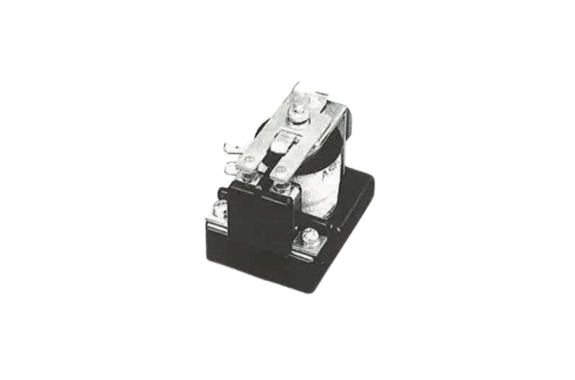
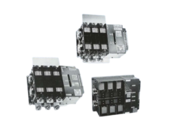
WashiON KYORITSU KEIKI CM2 Type DC Contactors
Manufacturer: WashiON KYORITSU KEIKI
Model: CM2
Features
- Supports forward and reverse switching of DC motors.
- Enables speed control for DC motors.
- Ideal for battery-powered vehicles such as:
Forklifts
Lift pallet vehicles
Fixed platform trucks
Specifications
| Main contact rated voltage | DC 48V | ||||
| Main contact rated current | 20A continuous | ||||
| Main contact arrangement | 1A | ||||
| Main contact capacity | Condition | Making | Breaking | Time constant | No. of times |
| Make & break capacity | 150 A | 150 A | L / R = 15 ms | 125 times | |
| Rated working current ※1 | 80 A | 20 A | L / R = 10 ms | 500,000 times | |
| Switching frequency | 1200 times / hour | ||||
| Coil | Voltage | DC 12V | DC 24V | DC 48V | |
| Current | 0.7 A | 0.36 A | 0.18 A | ||
| Resistance | 17.2 Ω | 66.6 Ω | 266.6 Ω | ||
| Power consumption | 8.5 W | ||||
| Insulation class | B class | ||||
| Min. pickup voltage | 70% or below of rated voltage (hot coil) | ||||
| Release voltage | 5% ~ 30% of rated voltage | ||||
| Insulation resistance | 5MΩ or above (DC500V megger) | ||||
| Withstand voltage | AC 1500V 50 / 60 Hz One minute | ||||
| Ambient temperature | −20°C ~ +60°C (no condensation) | ||||
| Relative humidity | 45% ~ 85% RH | ||||
| Vibration resistance (X, Y, Z directions) | 5G in excited state | 4G in non-excited state | |||
| Shock resistance (X, Y, Z directions) | 8G in excited state | 4G in non-excited state | |||
| Mechanical life | 5 million times | ||||
| Electrical life | 500,000 times (when used under condition of ※1) | ||||
| Weight | 0.25 kg | ||||
- [*1]The current and resistance values of the coil represent those at an ambient temperature of +20°C, and the tolerance on them is ±10%.
- [*2]The minimum pickup voltage represents that at an ambient temperature of +60°C and hot coil start.
■Relationship Between Current, Max. On Time And Duty Cycle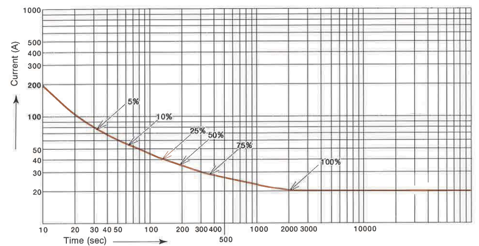
| Duty cycle | 5% ED | 10% ED | 25% ED | 50% ED | 75% ED | 100% ED |
| Current | 70 A | 50 A | 40 A | 35 A | 28 A | 20 A |
| Max. ON time | 30 sec | 60 sec | 120 sec | 180 sec | 360 sec | Continuous |
| OFF time | 570 sec | 540 sec | 360 sec | 180 sec | 120 sec | — |
■Overall Dimensions
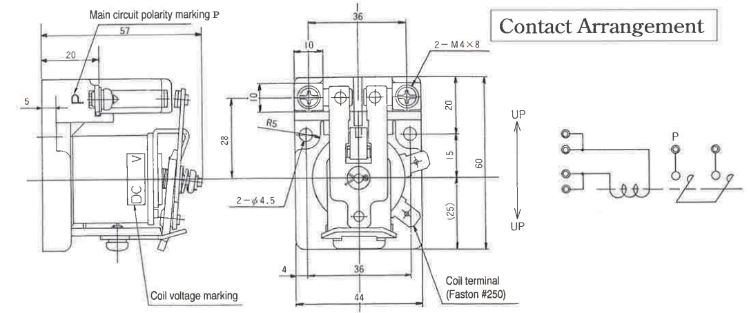
- [*1]Use 11 to 14 kg·cm as the tightening torque of the main circuit terminal (M4).
- [*2]Connect the positive pole (+) to the terminal marked with the main circuit polarity marking P.
(The contactor structure is such that arc is led out front by a built-in magnet.) - [*3]Install the DC contactor with the UP side up.
- [*4]Provide a space of 10 mm or more between contactors when two or more contactors are to be installed side by side.
Related Products
-
WashiON KYORITSU KEIKI MDM Series DC Contactor
-

WashiON KYORITSU KEIKI HTS Series High Speed Automatic Switch
-
WashiON KYORITSU KEIKI SSK Series LEF and LEH Type Automatic Transfer Switches
-

WashiON KYORITSU KEIKI On-delay Timer for Controlling DC Contactors
-

WashiON KYORITSU KEIKI EMS Models Emergency Switch
-

WashiON KYORITSU KEIKI Connectors and Stations for Boosting Charging Automated Guided Vehicles
REQUEST QUOTATION

PAYMENT

LINK


