WashiON KYORITSU KEIKI CO.
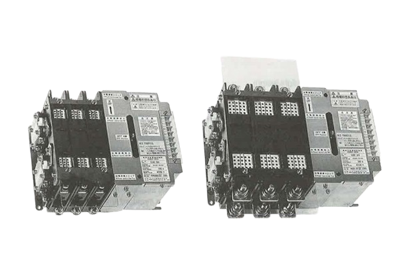
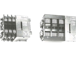
WashiON KYORITSU KEIKI SSK Series NE Type Automatic Transfer Switches
Manufacturer: WashiON KYORITSU KEIKI
Model: SSK Series
Features
- Capable of neutral stop operation.
- Compact and lightweight design.
- Available in a broad variety of models.
Specifications
| Type | |||||||||||
|---|---|---|---|---|---|---|---|---|---|---|---|
| 606 E | 61 E | 62 E | 64 E | 66 E | 68 E | 610 E | |||||
| Rated Voltage | 660VAC/140VDC | ||||||||||
| Rated current | 60A | 100A | 200A | 400A | 600A | 800A | 1000A | ||||
| Throw | Double throw (D) | ||||||||||
| Connection | Front (F), Back (B) | ||||||||||
| Weight Front (Back) | 2 P | 7.5kg (6.5 Kg) | 9 kg (6.7 Kg) | 15 kg (13.0 kg) | 45 kg (35.0 kg) | 50 kg (38.0 kg) | |||||
| 3 P | 9 kg (8.01 Kg) | 11 kg (7.6 Kg) | 18 kg 16.0 kg) | 53 kg (43.0 kg) | 60 kg (48.0 Kg) | ||||||
| 4 P | 10.5kg (9.5 kg) | 13 kg (8.5 kg) | 21 kg (19.0 kg) | 61 kg (51.0 kg) | 70 kg (58.0 kg) | ||||||
| Control current | Make | 2 P 3 P | 100VDC | 3.0 A | 4.0 A | 4.4 A | 5.2 A | 6.3 A | |||
| 100VAC | 3.2 A | 4.4 A | 5.2 A | 6.2 A | 7.2 A | ||||||
| 200VAC | 1.8 A | 2.4 A | 2.7 A | 3.2 A | 3.6 A | ||||||
| 4 P | 100VDC | 4.0 A | 4.3 A | 6.0 A | 6.3 A | 7.1 A | |||||
| 100VAC | 4.4 A | 5.0 A | 7.0 A | 7.2 A | 8.1 A | ||||||
| 200VAC | 2.4 A | 2.5 A | 3.5 A | 3.6 A | 4.1 A | ||||||
| Trip | 2P 3P 4P | 100VDC | 0.8 A | 1.0 A | 1.1 A | 1.5 A | 2.1 A | ||||
| 100VDC | 1.0 A | 1.2 A | 1.2 A | 1.6 A | 2.4 A | ||||||
| 100VDC | 0.5 A | 0.6 A | 0.6 A | 0.8 A | 1.2 A | ||||||
| Coil insulation class | A class (short time rating) | ||||||||||
| Withstand Voltage | Main circuit | 2500V AC, one minute (50/60 Hz) | |||||||||
| Control circuit | 2000V AC, one minute (50/60 Hz) | ||||||||||
| Short time current capacity (fsec during conduction) | 5 kA | 10 kA | 12 kA | 15 kA | 22 kA | ||||||
| Short peak current | 12 kA | 25 kA | 30 kA | 37 kA | 50 kA | ||||||
| Make and break capacity | AC 3 class (10le make, 8le break Cos φ=0.35) DC 1 class (1.1le make, 1.1le break L/R=1ms) | ||||||||||
| Life | Class 4 (mechanical life: 250,000 times, electrical life: 50,000 times) | ||||||||||
| Switching frequency | No. 4 (150 times/hr) | ||||||||||
| Switching characteristics (at rated voltage) | Opening time | 0.030 sec | 0.035 sec | 0.045 sec | 0.060 sec | 0.065 sec | |||||
| Switching time | 0.028 sec | 0.030 sec | 0.040 sec | 0.050 sec | 0.050 sec | ||||||
| Auxiliary control make & break capacity | Max. 250VAC 15A, 110VDC 5A, Min. 24VDC 0.1A | ||||||||||
| Notes | 1 | Weight represents that of F Types. | Weight represents that of Back (B) Types. | ||||||||
| 2 | Even with the back connection type, front wiring is to be performed for the control citcuit and auxillary circuit. | ||||||||||
| 3 | Make time is the time from control signal ON to contact making. | ||||||||||
| Trip time is the time from control signal ON to contact breaking. | |||||||||||
| Type | |||||||||||
|---|---|---|---|---|---|---|---|---|---|---|---|
| 612 E | 616 E | 620 E | 630 E | 640 E | 650 E | ||||||
| Rated Voltage | 660VAC/140VDC | ||||||||||
| Rated current | 1200A | 1600A | 2000A | 3000A | 4000A | 5000A | |||||
| Throw | Double throw (D) | ||||||||||
| Connection | Front (F), Back (B) | Back(B) | |||||||||
| Weight Front (Back) | 2 P | 71kg (k48.0g) | (100kg) | ( 110kg) | (170kg) | (190kg) | |||||
| 3 P | 80kg (58.0kg) | (150kg) | (150kg) | (210kg) | (270kg) | ||||||
| 4 P | 98kg (70.0kg) | (190kg) | (190kg) | (250kg) | (350kg) | ||||||
| Control current | Make | 2 P 3 P | 100VDC | 7.1 A | 5.2 A | 12.2 A | 13.1 A | 19.0 A | |||
| 100VAC | 8.1 A | 6.4 A | 13.9 A | 16.1 A | 22.3 A | ||||||
| 200VAC | 4.1 A | 3.4 A | 7.1 A | 7.7 A | 10.9 A | ||||||
| 4 P | 100VDC | 9.7 A | 12.2 A | 20.4 A | 24.0 A | 31.4 A | |||||
| 100VAC | 11.5 A | 13.9 A | 25.0 A | 28.3 A | 36.9 A | ||||||
| 200VAC | 5.6A | 7.1 A | 12.6 A | 14.2 A | 18.1 A | ||||||
| Trip | 2P 3P 4P | 100VDC | 2.5 A | 4.2 A | 5.3 A | 8.2 A | 12.5 A | ||||
| 100VDC | 2.8 A | 4.5 A | 6.2 A | 9.5 A | 15.1 A | ||||||
| 200VDC | 1.4 A | 2.4 A | 3.9 A | 5.2 A | 7.1 A | ||||||
| Coil insulation class | A class (short time rating) | ||||||||||
| Withstand Voltage | Main circuit | 2500V AC, one minute (50/60 Hz) | |||||||||
| Control circuit | 2000V AC, one minute (50/60 Hz) | ||||||||||
| Short time current capacity (fsec during conduction) | 25 kA | 35 kA | 50 kA | 50 kA | 50 kA | ||||||
| Short peak current | 55 kA | 60 kA | 80 kA | 100 kA | 120 kA | ||||||
| Make and break capacity | AC 3 class (10le make, 8le break Cos φ=0.35) DC 1 class (1.1le make, 1.1le break L/R=1ms) | AC 2 class (4le make, 4le break Cos φ=0.65 ) | |||||||||
| Life | Class 5 (mechanical life: 250,000 times, electrical life: 50,000 times) | (mechanical life: 10,000 times, electrical life: 5,000 times) | |||||||||
| Switching frequency | No. 4 (150 times/hr) | No. 5 (150 times/hr) | |||||||||
| Switching characteristics (at rated voltage) | Make | 0.07 sec | 0.085 sec | 0.09 sec | 0.10 sec | 0.12 sec | |||||
| Trip | 0.06 sec | 0.065 sec | 0.07 sec | 0.08 sec | 0.09 sec | ||||||
| Auxiliary control make & break capacity | Max. 250VAC 15A, 110VDC 5A, Min. 24VDC 0.1A | ||||||||||
| Notes | 1 | Weight represents that of Back (B) Types. | |||||||||
| 2 | Even with the back connection type, front wiring is to be performed for the control citcuit and auxillary circuit. | ||||||||||
| 3 | Make time is the time from control signal ON to contact making. | ||||||||||
| Trip time is the time from control signal ON to contact breaking. | |||||||||||
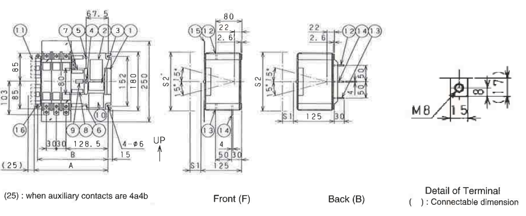
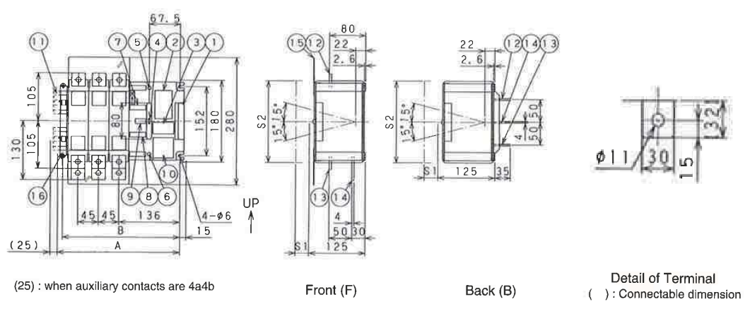
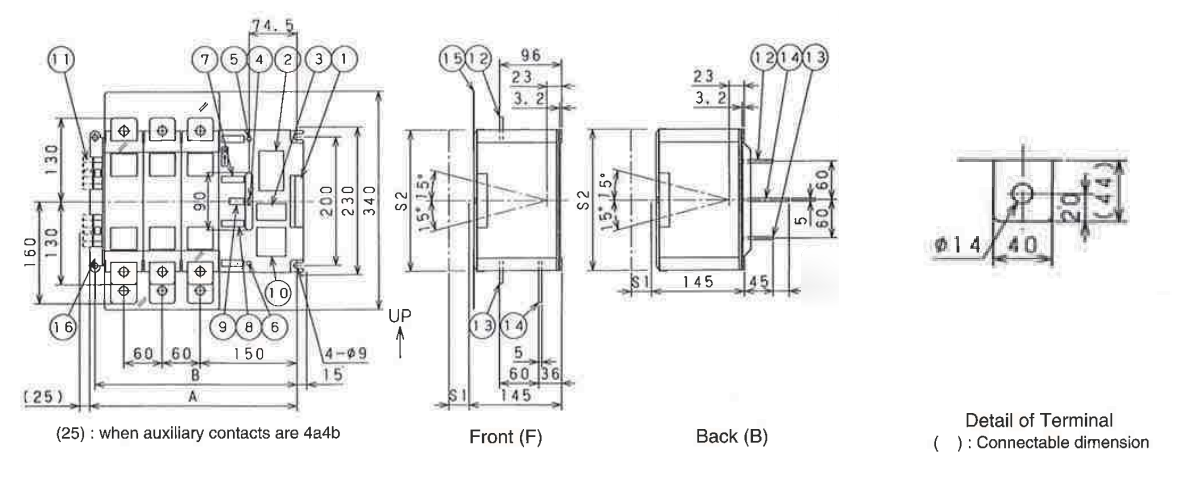
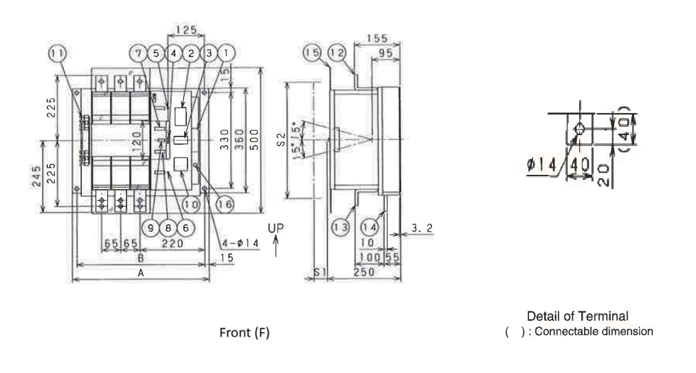
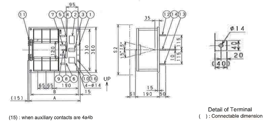
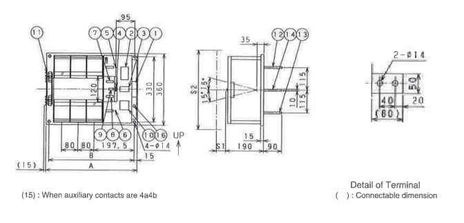
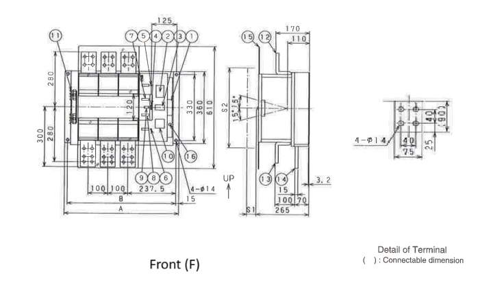
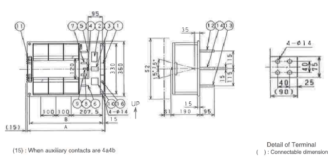
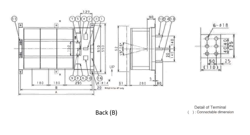
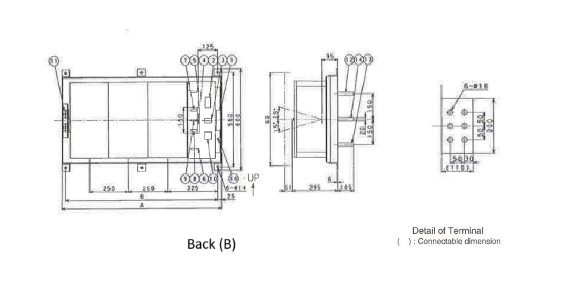
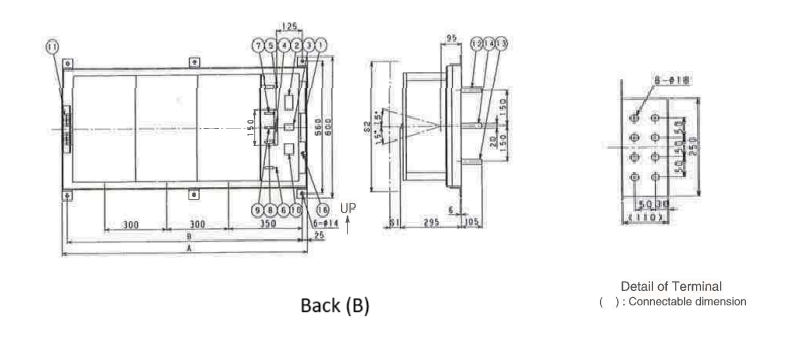
Overall Dimensions
- Control circuit terminal block (M3.5)
- Safety label
- Manual operation nameplate
- Manual closing handle inlet
- A power supply manual tripping pushbar inlet
- B power supply manual tripping pushbar inlet
- A power supply closing marking
- B power supply closing marking
- OFF position marking
- Model nameplate
- Auxiliary circuit terminal (M4)
- A power supply main circuit terminal
- B power supply main circuit terminal
- Load main circuit terminal
- Main circuit terminal cover (Front only)
- Earth terminal (400A and below: also for mounting use)
♦606NE, 61NE
| Dimensions | A | B | Arc space | ||
|---|---|---|---|---|---|
| S 1 | S 2 | ||||
| Poles | 250V | 660V | |||
| 2P | 200 | 185 | 30 | 60 | 180 |
| 3P | 230 | 215 | |||
| 4P | 260 | 245 | |||
♦62NE
| Dimensions | A | B | Arc space | ||
|---|---|---|---|---|---|
| S 1 | S 2 | ||||
| Poles | 250V | 660V | |||
| 2P | 230 | 215 | 30 | 60 | 180 |
| 3P | 275 | 260 | |||
| 4P | 320 | 305 | |||
♦64NE
| Dimensions | A | B | Arc space | ||
|---|---|---|---|---|---|
| S 1 | S 2 | ||||
| Poles | 250V | 660V | |||
| 2P | 275 | 255 | 30 | 60 | 220 |
| 3P | 335 | 315 | |||
| 4P | 395 | 375 | |||
♦66NE Front (F)
| Dimensions | A | B | Arc space | ||
|---|---|---|---|---|---|
| S 1 | S 2 | ||||
| Poles | 250V | 660V | |||
| 2P | 400 | 370 | 30 | 45 | 400 |
| 3P | 465 | 435 | |||
| 4P | 530 | 500 | |||
♦66NE Back (B)
| Dimensions | A | B | Arc space | ||
|---|---|---|---|---|---|
| S 1 | S 2 | ||||
| Poles | 250V | 660V | |||
| 2P | 340 | 310 | 30 | 45 | 400 |
| 3P | 405 | 375 | |||
| 4P | 470 | 440 | |||
♦68NE, 610NE Front (F)

| Dimensions | A | B | Arc space | ||
|---|---|---|---|---|---|
| S 1 | S 2 | ||||
| Poles | 250V | 660V | |||
| 2P | 430 | 400 | 30 | 45 | 400 |
| 3P | 510 | 480 | |||
| 4P | 590 | 560 | |||
♦68NE, 610NE Back (B)
| Dimensions | A | B | Arc space | ||
|---|---|---|---|---|---|
| S 1 | S 2 | ||||
| Poles | 250V | 660V | |||
| 2P | 370 | 340 | 30 | 45 | 400 |
| 3P | 450 | 420 | |||
| 4P | 530 | 500 | |||
♦612NE, 616NE Front (F)
| Dimensions | A | B | Arc space | ||
|---|---|---|---|---|---|
| S 1 | S 2 | ||||
| Poles | 250V | 660V | |||
| 2P | 470 | 440 | 30 | 45 | 400 |
| 3P | 570 | 540 | |||
| 4P | 670 | 640 | |||
♦612NE, 616NE Back (B)
| Dimensions | A | B | Arc space | ||
|---|---|---|---|---|---|
| S 1 | S 2 | ||||
| Poles | 250V | 660V | |||
| 2P | 410 | 380 | 30 | 45 | 400 |
| 3P | 510 | 480 | |||
| 4P | 610 | 580 | |||
♦620NE

| Dimensions | A | B | Arc space | ||
|---|---|---|---|---|---|
| S 1 | S 2 | ||||
| Poles | 250V | 660V | |||
| 2P | 545 | 505 | 30 | 45 | 500 |
| 3P | 680 | 640 | |||
| 4P | 815 | 775 | |||
♦630NE
| Dimensions | A | B | Arc space | ||
|---|---|---|---|---|---|
| S 1 | S 2 | ||||
| Poles | 250V | 660V | |||
| 2P | 640 | 600 | 30 | 45 | 500 |
| 3P | 820 | 780 | |||
| 4P | 1000 | 960 | |||
♦640NE
| Dimensions | A | B | Arc space | ||
|---|---|---|---|---|---|
| S 1 | S 2 | ||||
| Poles | 250V | 660V | |||
| 2P | 780 | 730 | 30 | 50 | 550 |
| 3P | 1030 | 980 | |||
| 4P | 1280 | 1230 | |||
♦650NE
| Dimensions | A | B | Arc space | ||
|---|---|---|---|---|---|
| S 1 | S 2 | ||||
| Poles | 250V | 660V | |||
| 2P | 880 | 830 | 30 | 50 | 550 |
| 3P | 1180 | 1130 | |||
| 4P | 1480 | 1430 | |||
Panel Finish Dimensions
| Type | 606NE 61NE | 62NE | 64NE | 66NE | 68NE,610NE | 612NE,616NE | 620NE | 630NE | 640NE | 650NE | ||||
|---|---|---|---|---|---|---|---|---|---|---|---|---|---|---|
| Front | Back | Front | Back | Front | Back | |||||||||
| B | 2P | 185 | 215 | 255 | 370 | 310 | 400 | 340 | 440 | 380 | 505 | 600 | 730 | 830 |
| 2P | 185 | 215 | 255 | 370 | 310 | 400 | 340 | 440 | 380 | 505 | 600 | 730 | 830 | |
| 2P | 185 | 215 | 255 | 370 | 310 | 400 | 340 | 440 | 380 | 505 | 600 | 730 | 830 | |
| J | 2P | 185 | 215 | 255 | 370 | 310 | 400 | 340 | 440 | 380 | 505 | 600 | 730 | 830 |
| 2P | 185 | 215 | 255 | 370 | 310 | 400 | 340 | 440 | 380 | 505 | 600 | 730 | 830 | |
| 2P | 185 | 215 | 255 | 370 | 310 | 400 | 340 | 440 | 380 | 505 | 600 | 730 | 830 | |
| I | 185 | 215 | 255 | 370 | 310 | 400 | 340 | 440 | 380 | 505 | 600 | 730 | 830 | |
| I | 185 | 215 | 255 | 370 | 310 | 400 | 340 | 440 | 380 | 505 | 600 | 730 | 830 | |
| I | 185 | 215 | 255 | 370 | 310 | 400 | 340 | 440 | 380 | 505 | 600 | 730 | 830 | |
| I | 185 | 215 | 255 | 370 | 310 | 400 | 340 | 440 | 380 | 505 | 600 | 730 | 830 | |
| I | 185 | 215 | 255 | 370 | 310 | 400 | 340 | 440 | 380 | 505 | 600 | 730 | 830 | |
- N: Distance to right-hand terminal.
- J,K and L apply to the back type (B).
- 6-M for 630NE(4P), 640NE and 650NE
Related Products
-

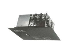
WashiON KYORITSU KEIKI CF3-TX Series Power Relay
-
WashiON KYORITSU KEIKI SSK Series E Type Automatic Transfer Switches
-

WashiON KYORITSU KEIKI On-delay Timer for Controlling DC Contactors
-
WashiON KYORITSU KEIKI SSK Series EF Type Automatic Transfer Switches
-
WashiON KYORITSU KEIKI MDM Series DC Contactor
-
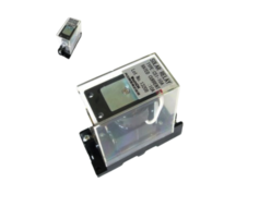
WashiON KYORITSU KEIKI CS1-10A Type Solar Relay
REQUEST QUOTATION

PAYMENT

LINK


