Japan, Sawada
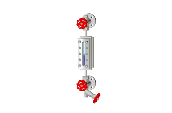
Sawada T-20 type Level gauge – See through type Level Gauge
Made in Japan
Manufacturer: Sawada Manufacturing Co., Ltd
Model: T-20 type
This level gauge has a structure in which reinforced gauge glasses are placed on the front and back of the gauge body, sandwiched between covers and tightened with bolts so that the liquid level can be seen through the gauge glasses.
Features
- connectioin type: Flange・Screw・Socket
- Maximum working pressure: 4.0 MPa
- Maximum operating temperature: 350℃
- Material: SF440A, SUS304/316/316L
- Installation length: 285-3000mm
Visibility
- The surface of the liquid, the interface between the two liquids that do not mix, and the color of the liquid can be visualized through the two gauge glasses.
- If it is difficult to see the liquid level in a clear liquid or in a dark place, installing a lighting device behind the level gauge will make the liquid level easier to see.
Standard dimension table (single type)
| glass count | gauge glass length | T-20 type | |
| Visible length (VL) | Installation length (C.to.C.) | ||
| No.0B | 90 | 70 | 285 |
| No.1B | 115 | 95 | 310 |
| No.2B | 140 | 120 | 335 |
| No.3B | 165 | 141 | 355 |
| No.4B | 190 | 166 | 380 |
| No.5B | 220 | 196 | 410 |
| No.6B | 250 | 226 | 440 |
| No.7B | 280 | 256 | 470 |
| No.300B | 300 | 276 | 490 |
| No.8B | 320 | 296 | 510 |
| No.9B | 340 | 316 | 530 |
| No.400B | 400 | 376 | 590 |
(Note) 1. Gauge glass dimensions conform to JIS B 8211. 2. The installation length is the minimum value. 3. The installation length is the dimension for the valve model KS20.
Standard dimension table (compound type)
| Glass count x Number of compounds | T-20 type | |
| Visible length (VL) | Installation length (C.to.C.) | |
| No.5B×2 | 437 | 650 |
| No.6B×2 | 497 | 710 |
| No.7B×2 | 557 | 770 |
| No.300B×2 | 597 | 810 |
| No.8B×2 | 637 | 850 |
| No.9B×2 | 677 | 895 |
| No.6B×3 | 768 | 985 |
| No.7B×3 | 858 | 1075 |
| No.300B×3 | 918 | 1135 |
| No.8B×3 | 978 | 1195 |
| No.9B×3 | 1038 | 1255 |
| No.7B×4 | 1159 | 1375 |
| No.300B×4 | 1239 | 1455 |
| No.8B×4 | 1319 | 1535 |
| No.9B×4 | 1399 | 1615 |
| No.7B×5 | 1460 | 1675 |
| No.300B×5 | 1560 | 1775 |
| No.8B×5 | 1660 | 1875 |
| No.9B×5 | 1760 | 1975 |
| No.300B×6 | 1881 | 2095 |
| No.8B×6 | 2001 | 2215 |
| No.9B×6 | 2121 | 2335 |
| No.300B×7 | 2202 | 2415 |
| No.8B×7 | 2342 | 2555 |
| No.9B×7 | 2482 | 2695 |
(Note) 1. Mounting length is the dimension for valve type KS20. 2. The installation length is the minimum value.
3. The length of the intermediate invisible part is T-10 type/TP type = 40mm, T-20/ET-20 type = 45mm. 4. If the number of compounds is large, it will be supported.
Standard dimension table (simultaneous type)
| Glass count x simultaneous number | T-20 type | |
| Visible length (VL) | Installation length (C.to.C.) | |
| No.7B×2 | 492 | 705 |
| No.300B×2 | 532 | 745 |
| No.8B×2 | 572 | 785 |
| No.9B×2 | 612 | 825 |
| No.7B×3 | 728 | 940 |
| No.300B×3 | 788 | 1000 |
| No.8B×3 | 848 | 1060 |
| No.9B×3 | 907 | 1120 |
| No.7B×4 | 964 | 1180 |
| No.300B×4 | 1044 | 1260 |
| No.8B×4 | 1124 | 1340 |
| No.9B×4 | 1204 | 1420 |
| No.300B×5 | 1300 | 1515 |
| No.8B×5 | 1400 | 1615 |
| No.9B×5 | 1500 | 1715 |
| No.300B×6 | 1556 | 1770 |
| No.8B×6 | 1676 | 1890 |
| No.9B×6 | 1796 | 2010 |
| No.300B×7 | 1812 | 2025 |
| No.8B×7 | 1952 | 2165 |
| No.9B×7 | 2092 | 2305 |
| No.8B×8 | 2228 | 2440 |
| No.9B×8 | 2388 | 2600 |
| No.8B×9 | 2504 | – |
| No.9B×9 | 2684 | – |
(Note) 1. The visible length is the maximum value, and the installation length is the minimum value. 2.The mounting length is for the valve model KS20-W. 3.

