Daiichi Keiki, Japan
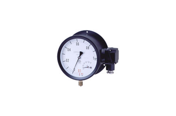
Daiichi Keiki SM Series Microswitch Contact Pressure Gauge
Manufacturer: Daiichi Keiki
Model: SM Series
Overview
In addition to functioning as a pressure gauge, this product incorporates microswitch contacts. Besides being able to read the indicated pressure, it operates ON (OFF) when it reaches a preset pressure value, which can be used for alarms such as buzzers and signal lamps, or for opening and closing small motor valves. Additionally, the version with microswitches for small currents can also be used for sequencer control.
Features
Unlike a pressure switch, this device allows for on-site reading of pressure indicators. It is equipped with a setting pointer, allowing contact operation at any set position. The microswitch uses snap action, so there is no chattering like with pointer contact points. The pressure elements for indication and contact are separate, so they have no interference.
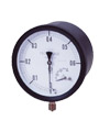
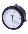
Pressure gauge with microswitch contacts Case appearance
▼100φ
| SMK-100 A Rimless type 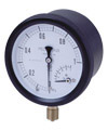 | SMK-100 B Type with rim for screw fixing 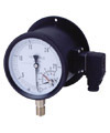 | SMK-100 D edged/pressure inlet rear type 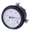 |
▼150φ
SMK-150 A
| SMK-150 B
| SMK-150 D-
|

Due to improvements to this product, specifications may change without prior notice.
Precautions
1. Since a microswitch is used for the contact, there is a unique pressure difference (dead band difference) between the contact activation and return.
The maximum is within 12%FS. Note that the dead band is fixed and cannot be changed.
2 The standard is designed for large currents, so it cannot be used for sequencer input. However, we can also manufacture products for small currents only for products with a size of 100φ, so please specify when ordering. (Order-made product)
3 If you use a large current type for sequencer input, please use it via an appropriate relay.
4 When using an electromagnetic switch or a high-wattage incandescent light bulb to turn it on or off, use a contact protection circuit to prevent flash discharge. This is because there is a large difference between steady current and inrush current depending on the type of load. Therefore, please pay careful attention to the ratings of each model. Inductive loads are especially problematic in DC circuits.
● Protection circuit/example (can be used for both AC and DC)
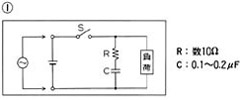 In small-load AC circuits, it may be better to connect C and R in series and connect S in parallel. In small-load AC circuits, it may be better to connect C and R in series and connect S in parallel.In that case, R: several tens to 100 Ω, C: 0.05 to 0.1μF | 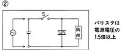 If used only in a DC circuit, it is OK to use a diode instead of a varistor. In that case, use one with sufficient reverse voltage resistance. |
● Inrush current/reference example
Relay: Approximately 4 to 5 times Motor: Approximately 5 to 10 times
Incandescent bulb: Approximately 10 to 15 times Solenoid: Approximately 10 to 20 times
When ordering
To ensure the prompt delivery of the requested product, please provide the following information:
(1) Model number (intended application, case type)
(2) Size, case exterior appearance
– Thread type and dimensions for connections
– Material of the contact liquid part
(3) Contact type
(4) Pressure span
Example of product naming:
(A) Model number: Outdoor use, metal-covered case
(B) Size: 100φ, Case exterior appearance: AU
Connection thread: G3/8B, Contact liquid part material: Brass
(C) Pressure span: 0~0.6MPa
(D) Contact type: Upper limit
Product name example
| SMK – 341A – 0.6MPa – H | |||
| (A) | (B) | (C) | (D) |
Product name (A)
| Model number | Sealability | Case type | Case material | Wire connection | Accuracy | Environmental temperature |
| S.M.K. | outdoor | metal screw lid case | AC black | Box connector (100 φ ) 6P terminal box (150 φ ) | ±1.6%FS | -5~45℃ |
Product name (B)
| Size | Case appearance shape | Screw (general use) | Screws (corrosion resistant) | Wetted parts material | |||||||
| G3/8B | R3/8 | G1/2B | R1/2 | G3/8B | R3/8 | G1/2B | R1/2 | ||||
| 100 | AU | – | 341A | 841A | 441A | 941A | 346A | 846A | 446A | 946A | General use Stock C3604 Bourdon tube C2680TW SUS316 (10MPa or more) Corrosion resistant use Stock SUS316 Bourdon tube SUS316 |
|---|---|---|---|---|---|---|---|---|---|---|---|
| B.U. | Mounting holes | 341B | 841B | 441B | 941B | 346B | 846B | 446B | 946B | ||
| DU | mounting bracket | 341DB | 841DB | 441DB | 941DB | 346DB | 846DB | 446DB | 946DB | ||
| 150 | AU | – | 361A | 861A | 461A | 961A | 366A | 866A | 466A | 966A | |
| B.U. | Mounting holes | 361B | 861B | 461B | 961B | 366B | 866B | 466B | 966B | ||
| DU | mounting bracket | 361DB | 861DB | 461DB | 961DB | 366DB | 866DB | 466DB | 966DB | ||
Product name (C) (D)
| Pressure span (MPa) | Contact type | ||
| Pressure | (0~0.1)~(0~60) | H | Upper limit |
| L | Lower limit | ||
| Vacuum | -0.1~0 | H.L. | Upper and lower limit |
| HH | Upper limit | ||
| Coupled | (-0.1~0.1)~(-0.1~2.5) | LL | Lower limit |
■ Electrical characteristics
| Size | For large current | For small current | Insulation withstand voltage | Contact disconnection difference | Operating value instrument difference | Reproducibility | ||||
| Rated voltage | Resistive load | Minimum load | Rated voltage | Resistive load | Minimum load | |||||
| 100 150 | AC250V | 10A | DC5V 160mA | AC125V | 0.1A | DC5V 1mA | 600 VAC for 1 minute between contacts of the same polarity 1500 VAC for 1 minute between terminals and cases | Within about 12%,usually 4-6% | Within ±3.0% FS | Within ±1.2% FS |
| DC30V | 0.1A | |||||||||
Due to improvements to this product, specifications may change without prior notice.
Related Products


REQUEST QUOTATION

PAYMENT

LINK


