Bolt & Nut, Hard Lock Nut, Japan
HARDLOCK Normal Type Nut Basic
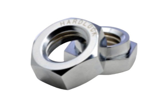
Product: Made in Japan
Manufacturer: HARDLOCK
Basic Normal Type: M6,M8,M10,M12,M14,M16,M18,M20,M22,M24,M27,M30,M33,M36,M39,M42,M45,M48,M52,M56,M64,M68,M72,M80,M85,M90,M95,M100,M105,M110,M115,M120,M125,M130
When you need fail safe fastening performance in the most demanding vibration environment, trust HARDLOCK Nuts (HLN) to meet or exceed your expectations. 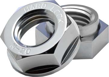
The primary reason for loosening in bolted joints is a drop in the initial clamp load occurring due to external forces such as impact and vibration, to battle this you need to eliminate the play (gap) between the threads of the bolt and nut.
Play will lead to not only shortened life span but also bolt brakeage which can result in catastrophic accidents.
We hit on the idea of utilizing the wedge principle, widely used in ancient Japanese architecture
Thanks to the design inspired by the principle, HLN completely eliminates the play between the threads and withstands severe vibration longer than any other nuts in the world.
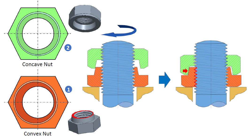
HLN consists of two nuts, the first nut 1 “Convex Nut” (clamping nut) has an eccentric protrusion on the upper surface.
The second nut 2 “Concave Nut” (locking nut) is designed with a concentric recess for locking the two nuts together.
By tightening the Concave Nut onto the Convex Nut, a strong perpendicular load will be applied to the bolt from both sides locking the HLN and making it resistant to vibrations and impacts from any direction.
After installing HLN you will realize a significant decrease in maintenance related work due to its exceptional self locking effect.
This will offer improvement of running cost, though HLN is a high end product, in combination with the advantage that it can be reused multiple times without almost any decrease in performance.
HLN is entirely made from metal only unlike other common self locking nuts and is available in various materials and surface treatment suitable for any environment.
HLN is predominantly used in applications which require safety at higher level in extreme conditions and environments, including but not limited to; Railway, Mining, Civil engineering and Machinery, just to name a few.
HARDLOCK NUT INSTALLATION

- Use a tightening tool (spanner, torque wrench etc.) to tighten the Convex Nut to the appropriate torque for the application
The convex nut has the same strength class as a regular hexagon nut and can therefore be tightened to its maximum limit.
2. Install the Concave nut onto the Convex nut manually by hand until it no longer turns (in other words, until prevailing torque is generated). Make sure that there is a gap of more than 1 thread pitch between the nuts.
If the gap is less than 1 pitch, there may be a chance that sufficient locking effect will not be produced so please refrain from using HARDLOCK NUT with the bolt. (The same conditions apply for reuse.)
3. Use a torque wrench to tighten the Concave nut with the recommended torque set by HARDLOCK Industry Co., Ltd
Even after correctly tightening the Concave nut with the torque within the range of recommended tightening torque, there may remain a gap between the nuts due to the tolerance of bolt diameter.
Even in this condition, sufficient locking effect is secured but the Concave nut can be further tightened to come into one sided contact or full contact even with more torque than the recommended torque to better ensure locking effect. If it is difficult to manage the tightening torque of the Concave nut, please use “one sided contact” as a guide for ensuring locking power.
When tightening the Concave nut on to the Convex nut, one side of the nuts will first come into contact, which gives an indication of sufficient locking effect (The Concave nut will slightly incline after the contact between the protrusion and the recess.).
When one sided contact is achieved, the tightening torque rapidly increases.
By applying additional torque , the nuts will come into full contact . This state produces the ultimate locking effect of the HARDLOCK NUT, but further tightening may cause the breakage of bolt threads. It is recommended to stop tightening the concave nut when the nuts come into full contact even though the applying torque is less than the maximum of recommended tightening torque.
Standard materials and coatings
| Material | Coating |
|---|---|
| Class 4/low-carbon steel (JIS SS400 equivalent) | Electrogalvanized (trivalent chromate) |
| Hot-dip galvanized (HDZ35) | |
| Class 8/medium-carbon steel (JIS S45C) | Manganese Phosphate coating |
| A2/stainless steel (JIS SUS304 or equivalent) | Unplated/plain |
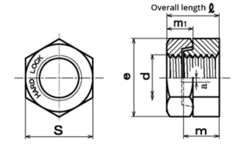
Dimensions in milimeters
| d | Pitch | Convex nut | Concave nut | Width across flats | e | Overall height | Unit Weight | ||||
|---|---|---|---|---|---|---|---|---|---|---|---|
| P | m | m1 | s | ℓ | g | ||||||
| Nominal Size | Coarse | Fine | Basic | Tolerance | Basic | Tolerance | Basic | Tolerance | Approx. | Approx | Approx |
| M6 | 1.0 | 0.75 | 5 | ±0.48 | 5 | ±0.48 | 10 | 0 -0.6 | 11.5 | 9.2 | 3.3 |
| M8 | 1.25 | 1.0 | 6.5 | ±0.58 | 6.5 | ±0.58 | 13 | 0 -0.7 | 15 | 12 | 8.6 |
| M10 | 1.5 | 1.25 | 8 | ±0.58 | 8 | ±0.58 | 17 | 0 -0.7 | 19.6 | 14.4 | 17.6 |
| M12 | 1.75 | 1.25 | 10 | ±0.58 | 10 | ±0.58 | 19 | 0 -0.8 | 21.9 | 17.9 | 27.3 |
| M14 | 2.0 | 1.5 | 11 | ±0.7 | 11 | ±0.7 | 22 | 0 -0.8 | 25.4 | 19.9 | 39 |
| M16 | 2.0 | 1.5 | 13 | ±0.9 | 12 | ±1.0 | 24 | 0 -0.8 | 27.7 | 23.2 | 52.8 |
| M18 | 2.5 | 1.5 | 15 | ±0.9 | 14 | ±1.0 | 27 | 0 -0.8 | 31.2 | 26.7 | 80 |
| M20 | 2.5 | 1.5 | 16 | ±0.9 | 15 | ±1.0 | 30 | 0 -0.8 | 34.6 | 28.2 | 105 |
| M22 | 2.5 | 1.5 | 18 | ±0.9 | 17 | ±1.0 | 32 | 0 -1.0 | 37.0 | 32.3 | 130 |
| M24 | 3.0 | 2.0 | 19 | ±0.9 | 18 | ±1.0 | 36 | 0 -1.0 | 41.6 | 33.9 | 180 |
| M27 | 3.0 | 2.0 | 21 | ±1.0 | 21 | ±1.0 | 41 | 0 -1.0 | 47.3 | 37.9 | 246 |
| M30 | 3.5 | 2.0 | 23 | ±1.0 | 23 | ±1.0 | 46 | 0 -1.0 | 53.1 | 41.9 | 375 |
| M33 | 3.5 | 2.0 | 25 | ±1.0 | 20 | 0 -1.5 | 50 | 0 -1.0 | 57.7 | 39.4 | 411 |
| M36 | 4.0 | 3.0 | 28 | ±1.0 | 21 | 0 -1.5 | 55 | 0 -1.2 | 63.5 | 41.9 | 532 |
| M39 | 4.0 | 3.0 | 30 | ±1.2 | 23 | 0 -1.5 | 60 | 0 -1.2 | 69.3 | 45.7 | 681 |
| M42 | 4.5 | 4.0 | 33 | ±1.2 | 25 | 0 -1.5 | 65 | 0 -1.2 | 75.0 | 50.2 | 892 |
| M45 | 4.5 | 4.0 | 35 | ±1.2 | 27 | 0 -1.5 | 70 | 0 -1.2 | 80.8 | 54.2 | 1,115 |
| M48 | 5.0 | 4.0 | 37 | ±1.2 | 29 | 0 -1.5 | 75 | 0 -1.2 | 86.5 | 58.2 | 1,393 |
| M52 | 5.0 | 4.0 | 41 | ±1.2 | 31 | 0 -1.5 | 80 | 0 -1.2 | 92.4 | 63.7 | 1,708 |
| M56 | 5.5 | 4.0 | 44 | ±1.2 | 34 | 0 -1.5 | 85 | 0 -1.4 | 98.1 | 68.7 | 2,047 |
| M64 | 6.0 | 4.0 | 50 | ±1.5 | 38 | 0 -1.5 | 95 | 0 -1.4 | 110 | 77 | 2,795 |
| M68 | 53 | ±1.5 | 40 | 0 -1.7 | 100 | 0 -1.4 | 115 | 81.1 | 3,480 | ||
| M72 | 57 | ±1.5 | 42 | 0 -1.7 | 105 | 0 -1.4 | 121 | 85.1 | 3,910 | ||
| M76 | 60 | ±1.5 | 46 | 0 -1.7 | 110 | 0 -1.4 | 127 | 92.1 | 4,440 | ||
| M80 | 63 | ±1.5 | 48 | 0 -1.7 | 115 | 0 -1.4 | 133 | 97.1 | 5,070 | ||
| M85 | 67 | ±1.5 | 50 | 0 -1.7 | 120 | 0 -1.4 | 139 | 101.1 | 5,630 | ||
| M90 | 71 | ±1.5 | 54 | 0 -2.0 | 130 | 0 -1.6 | 150 | 109.1 | 7,340 | ||
| M95 | 75 | ±1.5 | 57 | 0 -2.0 | 135 | 0 -1.6 | 156 | 115.1 | 8,150 | ||
| M100 | 79 | ±1.5 | 60 | 0 -2.0 | 145 | 0 -1.6 | 167 | 121.1 | 10,140 | ||
| M105 | 83 | ±1.8 | 63 | 0 -2.0 | 150 | 0 -1.6 | 173 | 127.4 | 11,140 | ||
| M110 | 87 | ±1.8 | 65 | 0 -2.0 | 155 | 0 -1.6 | 179 | 131.4 | 12,000 | ||
| M115 | 91 | ±1.8 | 69 | 0 -2.0 | 165 | 0 -1.6 | 191 | 139.4 | 14,780 | ||
| M120 | 95 | ±1.8 | 72 | 0 -2.0 | 170 | 0 -1.6 | 196 | 145.4 | 16,050 | ||
| M125 | 99 | ±1.8 | 76 | 0 -2.0 | 180 | 0 -1.6 | 208 | 153.4 | 19,410 | ||
| M130 | 103 | ±1.8 | 78 | 0 -2.0 | 185 | 0 -1.6 | 214 | 157.4 | 20,650 | ||
• External dimensions according to JIS B1181 (2004)/ISO 4032 (width across flats only)
• Threads screw tolerance according to JIS B0209 (2001)/ISO 965 6H
Tightening Torque Table Dimensions
| Nominal size | Pitch | Reference tightening torque for convex nut (same as general hex nut) *70% of the bolt yield point | Recommended tightening torque for the concave nut | ||||
|---|---|---|---|---|---|---|---|
| Class 4 (SS400 or equivalent) | Class 8 (S45C) | A2/stainless steel (JIS SUS304 or equivalent) | Common to all materials (Min – Max) | ||||
| 4.8 (320 N/mm2) | 8.8 (640 N/mm2) | A2-50 | A2-70 | ||||
| CR3 | HDZ35 | Manganese Phosphate coating | Plain | ||||
| M8 | 1.25 | – | – | – | – | – | 9–13 |
| M10 | 1.5 | – | – | – | – | – | 18–24 |
| M12 | 1.75 | – | – | – | – | – | 27–39 |
| M14 | 2.0 | 55 | 125 | 110 | 36 | 75 | 40–58 |
| M16 | 2.0 | – | – | – | – | – | 70–100 |
| M18 | 2.5 | 115 | 270 | 230 | 75 | 165 | 100–150 |
| M20 | 2.5 | – | – | – | 110 | 230 | 120–200 |
| M22 | 2.5 | – | – | – | 145 | 315 | 150–250 |
| M24 | 3.0 | – | – | – | 185 | 400 | 160–300 |
| M27 | 3.0 | – | – | – | 275 | 585 | 250–390 |
| M30 | 3.5 | – | – | – | 370 | 790 | 270–440 |
| M33 | 3.5 | 770 | 1,795 | 1,540 | 505 | 1,080 | 290–490 |
| M36 | 4.0 | 990 | 2,305 | 1,975 | 650 | 1,390 | 340–590 |
| M39 | 4.0 | 1,280 | 2,985 | 2,555 | 840 | 1,800 | 390–640 |
| M42 | 4.5 | 1,580 | 3,690 | 3,160 | 1,035 | 2,225 | 440–690 |
| M45 | 4.5 | 1,980 | 4,620 | 3,960 | 1,300 | 2,785 | 490–740 |
| M48 | 5.0 | 2,370 | 5,530 | 4,740 | 1,555 | 3,335 | 540–780 |
| M52 | 5.0 | 3,075 | 7,175 | 6,150 | 2,020 | 4,325 | 590–830 |
| M56 | 5.5 | 3,820 | 8,915 | 7,640 | 2,505 | 5,370 | 640–880 |
| M64 | 6.0 | 5,765 | 13,445 | 11,525 | 3,780 | 8,105 | 690–930 |
| M68 | 6,980 | 16,287 | 13,960 | 4,581 | 9,816 | Tighten about 1 turn after tightening manually | |
| M72 | 8,370 | 19,531 | 16,741 | 5,493 | 11,771 | ||
| M76 | 9,931 | 23,172 | 19,862 | 6,517 | 13,965 | ||
| M80 | 11,677 | 27,246 | 23,353 | 7,663 | 16,420 | ||
| M85 | 14,131 | 32,973 | 28,263 | 9,274 | 19,872 | ||
| M90 | 16,907 | 39,450 | 33,814 | 11,095 | 23,776 | ||
| M95 | 20,023 | 46,721 | 40,047 | 13,140 | 28,158 | ||
| M100 | 23,503 | 54,841 | 47,006 | 15,424 | 33,051 | ||
| M105 | 27,363 | 63,847 | 54,726 | 17,957 | 38,479 | ||
| M110 | 31,623 | 73,787 | 63,246 | 20,753 | 44,470 | ||
| M115 | 36,302 | 84,705 | 72,605 | 23,823 | 51,050 | ||
| M120 | 41,425 | 96,658 | 82,850 | 27,185 | 57,254 | ||
| M125 | 47,006 | 109,682 | 94,013 | 30,848 | 66,103 | ||
| M130 | 53,067 | 123,823 | 106,134 | 34,825 | 74,625 | ||
Related Products
-
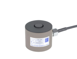
Showa Measuring Instruments CHM JCSS-calibration-compliant Load Cells For Force Testers
-
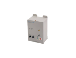
Kanetec EPS-215B Ep Chuck Master
-
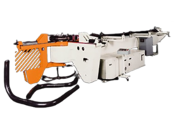
Chiyoda Kogyo RB-200 NC Tube Bender
-
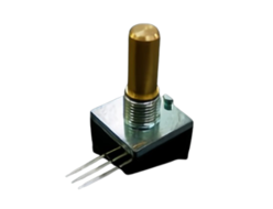
Tokyo Ko-on Denpa CP600 Series Variable Potentiometer
-
Chiyoda Seiki BA-3/BAS-3 Piping Take-out B Valve For Acetylene And LPG (with check valve)
-
Eight Tool TLS-7SD Taper Head


