Air Preparation Equipment, Japan, KONAN ELECTRIC
KONAN LVS5-02/LVD5-02 Lockup Valve
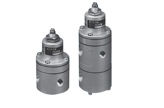
Product Made In Japan
Manufacturer: KONAN ELECTRIC
Model: LVS5-02/LVD5-02
This valve reacts to sudden drops in pneumatic line supply air pressure, maintaining the driven unit’s set pressure until the supply normalizes. It also locks the actuator to prevent unexpected movements if the supply pressure varies
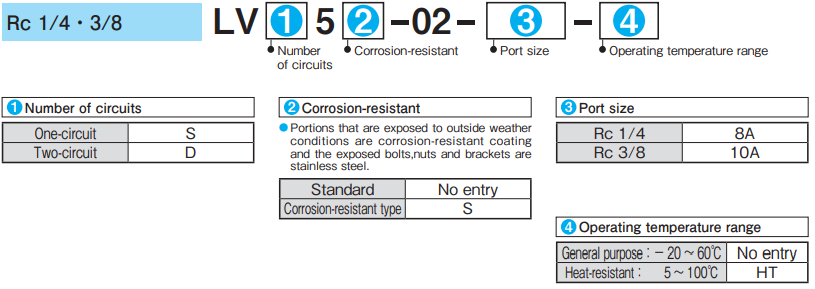
Model Code
Specifications
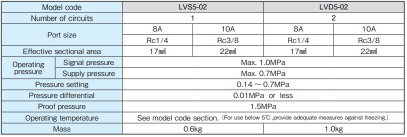
● For specifications other than those listed above, please contact us.
● In the event of use in high dry air over dew point − 40℃, please contact us.
Operation
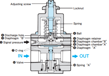
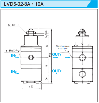
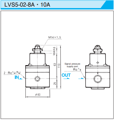
Signal pressure ❶ enters diaphragm chamber B ❷ and acts on diaphragm B ❸. When the signal pressure exceeds the spring force, it pushes diaphragm B upwards and causes ball ❹ to close the discharge hole ❻ in the diaphragm retainer ❺. At the same time, the signal pressure flows between diaphragm retainer ❺ and O ring ❼ to diaphragm chamber A ❽. It acts on diaphragm A (❾) and forces valve (⓫)open against the force of spring A (❿), thus completing the operating circuitIf the signal pressure falls below the spring’s force, the spring pushes diaphragm B down, opening discharge hole in the diaphragm retainer and linking diaphragm chambers B and A. This action discharges the signal pressure from diaphragm chamber A through the discharge hole. Once emptied, spring A’s force closes the valve, sealing the operating circuit and preserving the circuit’s pressure. In the two-circuit type (LVD5-02), circuits 1 and 2 run in parallel, with their respective diaphragm chambers A interconnected.
Standard type (2 circuits )
Standard type (1 circuit)
Operating Instructions
1. Fluid
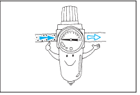
● Use only with clean fluids as dirt, wastes, etc. in the fluid may cause malfunctioning.
2. During operation
● Lockup valves are of the bleed type. Although a small amount of air will escape from the relief opening during operation, it will not cause any problems under normal use. To prevent air from escaping, apply a signal pressure more than 0.15MPa higher than the set pressure on the valve.
3. Pressure setting procedure
Step 1: Apply a signal pressure equal to the set pressure.(Valve opens.)
Step 2: Turn the adjusting screw clockwise to close the valve. This completes the pressure setting. (After the pressure setting is completed, a small amount of air will escape from the relief opening. However, this will not cause any problems under normal use.)
Step 3: Increase the signal pressure. ( Applying a signal pressure more than 0.05MPa higher than the set pressure will make operation more stable. To prevent air from escaping, apply a signal pressure more than 0.15MPa higher than the set pressure.)
- Kouei is a Distributor/Agent for KONAN.
- Other items of KONAN.
- Request the quotation for KONAN.
Related Products
-

Magnescale SL130 Ribbon Type Scale (Digiruler)
-
Chiyoda Tsusho C-16 Peeling Machine C-16 (Special Tool For Removing Anti-spatter Tubes)
-
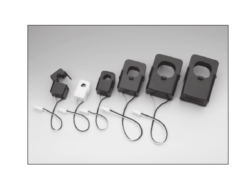
U_RD CTT-36-9SC AC Current Sensor
-
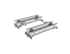
KITO Low-head End Carriage
-
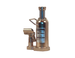
Eagle Jack (Konno Corporation) ED-100C Hydraulic Bottle Jack
-
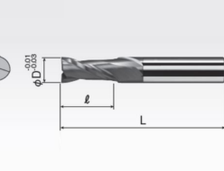
Okazaki Seiko SED2A Coated Solid Carbide Square Endmills (2 Flutes)


