Japan, Kyowa Electronic Instruments Co., Ltd.
Kyowa CTRS-100A Compact Recorder CTRS-100 Series Compact Recorder

Made in Japan
Manufacturer: Kyowa Electronic Instruments Co., Ltd.
Model: CTRS-100A Compact Recorder
- Modular for easy expansion and measurement of up to 128 channels
- High installation flexibility
Impact resistance: 490 m/s2(50 G) - Simultaneous sampling of all channels at 20 kHz (4 channels)
- Measurement of 100 channel at up to 1 kHz
- Wireless real-time monitoring is possible (when using a wireless LAN unit)
Compatible with CAN/CAN FD (when using a CAN input unit)
Feature
The compact recorder CTRS-100 series is compact, lightweight, and shock-resistant and supports various stress measurements regardless of installation location, from environments where space is limited and exposed to vibration and shock, such as motorcycle running tests and actual ship tests, to tabletop measurements.
Specification
connector
| USB connector | Micro USB Type-B |
|---|---|
| Remote control connection connector | Connect the remote control unit |
| External input/output connectors | Model: ECA.0B.307.CLN compatible connector: FGA.0B.307.CLAD52 |
| Operation switch | POWER |
|---|---|
| Indicator | Status LED SD card access indicator LED |
| Data recording media | Recommended by our company Industrial SD card SD standard: SDHC capacity: 4 GB, 16 GB Format: FAT32 (operation is not guaranteed when using an SD card other than the recommended product) |
| Communication Interface | USB (USB2.0 High Speed) Ethernet*1 |
Number of units consolidated
| Measuring unit | Up to 100 units can be connected to one CTRS-1A unit (7 channels in total) |
|---|---|
| Expansion Unit | Up to 100 units can be connected to one CTRS-1A, but two or more units of the same expansion unit cannot be connected together. |
Device-to-device synchronization
| Synchronization method | Connect the CTRS-100A using a synchronization unit and synchronization cable |
|---|---|
| Maximum number of syncs | Up to 100 CTRS-4A channels and up to 128 measurement channels can be synchronized |
| Acquired data | To the SD card of each unit or to the PC*2Acquired to |
Acquired data
| File destination | SD Card PC*2 |
|---|---|
| Data format | Republican Standard Format KS3 |
| Maximum data file size | 4 GB/1 data file (1 GB = 1,000,000,000 bytes)*3 |
| Data recovery | Online collection by PC or offline collection by reading SD card directly to PC |
Measurement condition setting method
| Online settings | Set by control software (PC) |
|---|---|
| Offline settings | Read and set the measurement condition settings in the SD card. |
Acquisition Mode
| manual | User operation to start and stop acquisition |
|---|---|
| Triggers (composite triggers) | Automatic acquisition by setting trigger conditions |
| International | Automatic acquisition is performed by setting the acquisition start time and acquisition interval. |
sampling
| method | Simultaneous sampling of all channels |
|---|---|
| frequency | 1,2,5 series 1,2,5,10,20,50,100,200,500,1k,2k,5k,10k,20k,50k,100kHz 2nSeries 4,8,16,32,64,128,256,512,1024,2048,4096,8192,16384,32768,65536 Hz Maximum sampling frequency that can be set: 100 kHz / number of measurement channels |
| External Clock | Use clock input from external device as sampling clock Frequency is set in 1Hz increments from 100Hz~1kHz Input a clock within 5% ± the set frequency Voltage level HIGH:2.4~5V, LOW:0~0.8V DUTY30~70% |
Trigger function
| Trigger Type | ・Analog input signal (analog trigger), external trigger input signal (non-voltage contact, open collector, voltage level HIGH: 2.4~5 V, LOW: 0~0.8 V signal ),manual (start acquisition by pressing the REC button while waiting for trigger) |
|---|---|
| Trigger Level | Can be set arbitrarily within the range of ±FS*4 |
| Trigas rope | Standing Up and Falling |
| Pre-trigger | The amount of data to be saved before the start trigger point can be set up to 524288 data/number of measurement channels. |
| Post-trigger | The amount of data to be saved after the end trigger point by specifying the amount of data can be set up to 524288 data/number of measurement channels. |
Backup function
| What to back up | Setting conditions, equilibrium adjustment value (zero suppressed value) |
|---|---|
| Save to | Internal Nonvolatile Memory |
External clock output
| Signal Level | Configurable inverting or non-inverting DC 5 V signal |
|---|---|
| division | The clock signal synchronized with the sampling clock can be divided and the output divider ratio can be set in the range of 1~65534. |
| Output Mode | Choose from Always output, Output only during acquisition, or Do not output |
Other functions
| Specify the number of acquired data | Automatically terminate acquisition after acquiring a specified number of data |
|---|---|
| Automatic power off recovery function*5 | During acquisition, if the power supply is interrupted due to a power outage or other reasons, you can choose whether to switch to battery operation and continue acquiring, or to close the file being acquired and then shut it down. If you select shutdown, you can choose whether to resume acquisition or enter a standby mode after power is restored. |
| Acquisition recovery function | Turn off the POWER switch during acquisition and choose whether to resume acquisition or wait when it is turned back on |
| File name appending | Automatically assign the file number or acquisition date and time to the file name of the acquired data |
| Trigger signal output | When the acquisition mode is trigger (combined trigger), waiting to output trigger signal: DC 5 V, acquiring: DC 0 V |
Measurement section specifications
| Maximum number of input channels | 4 |
|---|
Input connector
| Connector shape | NDIS4109 (Small 9-Pin Receptacle) Model: EPRC07-RX9FNDIS |
|---|---|
| Compatible plugs | NDIS4109 (Small 9-Pin Plug) Plug Model: EPRC07-P9MNDIS |
| Measurement object | Strain measurement: strain gauge*6,Strain gauge transducer voltage measurement: voltage |
|---|---|
| Compatible bridge resistance | Strain measurement: 2~120 when the bridge power supply is set to 1000 V Ω 5~350 Ω when the bridge power supply is set to 1000 V |
| Gauge rate | Strain measurement: 2.00 fixed |
| Bridge Power Supply/Sensor Power Supply | Strain measurement: DC 2 V, 5 V Voltage measurement: DC 2 V, 5 V *7 OFF (0 V) up to 1 mA output per channel |
| Input impedance | Voltage measurement: 3.6 MΩ±10% |
| Input Format | Balanced differential input |
Measuring range
| Setting method | Arbitrary range method and OFF |
|---|---|
| Configurable range | Strain measurement: Min: 1000×10-6 Strain Max: 50000×10-6 Strain voltage measurement: min: 1 V max: 50 V |
| Configuration steps | Strain measurement: ・1000~10000×10-6 Strain 100×10-6 Strain step ・10000~50000×10-6 Strain 1000×10-6 Strain step voltage measurement: ・1~10 V 0.1 V step・10~50 V 1 V step |
| Range accuracy | ± within 0.2%FS |
|---|---|
| Nonlinearity | ± within 0.1%FS |
Temperature stability
| zero | Strain measurement: ±(0.009%FS+0.9×10⁻⁶Strain) / within °C Voltage measurement: ± ( 0.009%FS + 0.21 mV) / °C |
|---|---|
| sensitivity | Within ±0.03%/°C |
Time stability
| zero | Strain measurement: ±(0.09%FS+9×10⁻⁶Strain)/voltage measurement within 8H: ±(0.09%FS + 0.1 mV)/within 8H |
|---|---|
| sensitivity | ±0.3%/8H or less |
Equilibrium adjustment
| establishment | Select from ON, OFF, NONE for each channelON: Performs balance adjustment and sets the measured value to zeroOFF: NONE does not perform new balance adjustment: Disables balance adjustment and confirms the initial unbalanced value (input voltage) |
|---|---|
| How to operate | Balance execution operation from control software*8 or BAL switch operation of the dedicated remote control |
| Adjustment method | Autobalance (stored in nonvolatile memory) |
| Adjustment range | Strain measurement: ±10000×10-6 Voltage measurement within strain: within ±10 V |
| precision | Strain measurement: ± (0.1%FS + 2×10⁻⁶ Strain) voltage measurement: within ±0.1%FS |
| NONE precision | Strain measurement: within ±1%FS*9 Voltage measurement: within ±0.2%FS |
| Input Range | Strain measurement: ±60000×10-6 Voltage measurement within strain: within ±60 V |
|---|---|
| Common-mode input voltage range | Voltage measurement: within ±20 V |
Absolute maximum rating
| input | Strain measurement: ±5 V Voltage measurement: ±70 V |
|---|
| Response frequency | DC~20 kHz,-3±1 dB( at 20 kHz) |
|---|
Lowpass Filter
| Transfer characteristics | 5th Butterworth |
|---|---|
| Cutoff frequency | 10,20,50,100,200,500,1k,2k,5k,10k Hz and FLAT*10,AUTO*11 |
| Amplitude ratio at cutoff point | -3±1 dB |
| Attenuation characteristics | -30±3 dB/oct.*12 |
High-pass filter
| Cutoff frequency | 0.2,1 Hz and OFF |
|---|
AD conversion
| resolution | 24-bit |
|---|---|
| method | Simultaneous sampling of all channels |
| Indicator | Channel Status LED |
|---|
Other functions
| Input resistance check function | A-C resistance check function accuracy ± within 2 % Used for sensor connection check |
|---|---|
| TEDS | Read TEDS information and reflect it in measurement conditions*8 |
General Specifications
| Power connector | Model: ECP.1S.302.CLL |
|---|---|
| Power supply voltage range | DC 10~30 V |
| Power consumption | Approx. 3.5 W (with 12 VDC supply) |
| Operating temperature and humidity range | -10~50 °C,20~90%(non-condensing) |
| Storage temperature range | -20~60 ℃ |
| Vibration resistance | 49.0 m/s2(5 G),5~200 Hz |
| Impact resistance | 490 m/s2(50 G), 11 ms or less, half-sine wave |
| Degree of protection | IP50 (JIS C 0920 / IEC 60529) |
| External dimensions | 53.2(W) × 92(H) × 94(D) mm (excluding protrusions and protectors) |
| mass | about 420 g |
| Conformity directives | EMC Directive 2014/30/EU RoHS Directive 2011/65/EU, (EU )2015/863 (10 substances) |
| pin | GND pin M3 bind |
| Utility Nut | Size:M4, 12 places |
| *1 A separate synchronization unit and dedicated communication cable are required *2 Only during online control by PC*3 Maximum acquisition time depends on the number of measurement channels and sampling frequency [seconds] = 1,000,000,000 ÷Number of measurement channels÷ sampling frequency *4 Analog input signal only *5 Only when the battery unit is connected*6 A separate bridge box is required *7 When the sensor power supply is DC 2 V, the positive side of the sensor power supply is +1 V, the negative side is -1 V sensor power supply DC 5 V, the positive side of the sensor power supply is +2.5 V, the negative side is -2.5 V *8 Only when online control by PC*9 When the bridge resistance is 350 Ω*10 When FLAT is set, the cutoff frequency is set to approximately 25 kHz. However, the specification of the amplitude ratio at the cut-off point does not apply*11 The cut-off frequency at the time of AUTO setting is set to approximately 1/4 of the set sampling frequency*12 Cut-off frequency exceeding 5 kHz is excluded * The measurement unit specification is applied to a stable temperature state after a preheating time of 30 minutes. |
| Standard Accessories | Connecting connector cap for female 2 SD card 4GB USB Cable CTRS DC Power Cable P-79 Ground wire P-78 Ball Point Driver Input Connector Cap 4 |
|---|---|
| Sold separately | UIA345-12-L-JP CTRS AC Adapter UNI345-1238-L-US CTRS AC Adapter for USA Various Measurement Units Various Expansion UnitsRemote Control Unit Connector Cap BRA.0B.200.PCSG Connector Cap for Remote Control Connection Connector/External Input/Output Connector BRA.1B.200.PCSG U-136 4109P-S32-7 (6-Core Shield) U-137 4109P-BNC Plug U-129 4109P-BNC Jack forPower ConnectorU-138 4109P-R05 Jack U-133 EXTERNAL I/O Cable SD Card (4GB, 16GB) DCS-100A Dynamic Data Acquisition Software (Ver.04.68 or later) |
Dimensions

Related Products
-
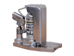
Eagle Jack (Konno Corporation) G-40LC Hydraulic Claw Jack
-

Saitamaseiki AK-104SR Grinders and single action sanders
-
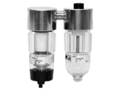
Ross Asia Miniature series Port sizes 1/8″ and 1/4″. Flow rates up to 19 scfm (538 l/min)
-
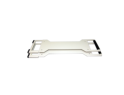
Kyowa YC-HANDLE YC Handle Other Accessories
-

Fujii Denko R-502-D-PT Harness & Lanyard
-
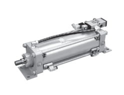
KONAN MS665 Pneumatic Cylinders With 5-port Solenoid Valve And Reed Switch
REQUEST QUOTATION

PAYMENT

LINK


