Japan, Nachi
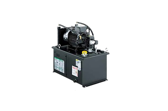
Nachi NSPi Series Inverter Drive Hydraulic Unit
Made in: Japan
Manufacturer: NACHI
Model: NSPi Series (NSP-10E-15V*A*-21, NSP-10E-22V1A*-21, NSP-20E-15V1A*-21, NSP-20E-22V1A*-21)
Features of NSPi Series
Easy Operation and Reliable Performance
Immediate start just by turning on the power
The inverter drive NSPi unit can be started easily just by turning on the power.
Just push a single button to operate at maximum energy savings after pressure is adjusted.
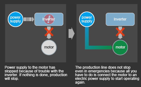
Production lines keep running
Production lines continue running even if there is trouble with the inverter because it is based on our reliable NSP unit and keeps running as a regular NSP unit.
Perfomance
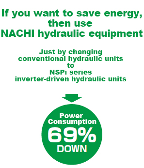
Energy-saving effect
Power Consumption Reduced by Approximately 69%
(as compared to NACHI-Fujikoshi’s standard hydraulic units while dwelling)
The base NSP unit consumes about 40% less energy than NACHI-Fujikoshi’s standard hydraulic units. By adding the inverter drive we increase energy savings to approximately 69% as compared to NACHI-Fujikoshi’s standard hydraulic units.
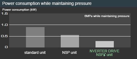
Power rate 40% down
As compared to NACHI-Fujikoshi’s standard hydraulic units, the NSP unit cuts 25% and the inverter drive NSPi unit cuts another approximately 40% from energy bills.
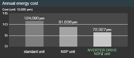
Reduces annual CO2 emissions by approximately two tons
The inverter drive NSPi unit emits about 42% less CO2 than NACHI-Fujikoshi’s standard hydraulic units.
Equivalent to two hectares of forest
Method for calculating energy costs and CO2 emissions
| an annual operation time | 8000hour | electric power unit price | 15yen/kWh |
| maintaining pressure | 17houur/day | CO2 Emission factors | 0.555kgCO2/kWh |
| Discharge | 5hour/day | ||
*CO2 emissions factor: default value set by Ministry of Economy, Trade and Industry & Ministry of the Environment Ordinance Number 3, 2006.
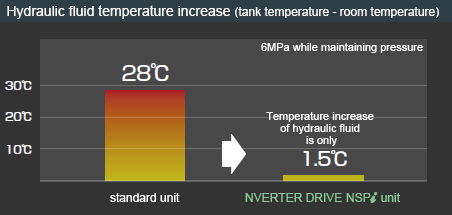
Reduce increase in hydraulic fluid temperature
1.5°C increase in ambient temperature
The NSPi series benefits your entire system by lowering oil temperature to improve machining accuracy, lengthen the life of seals and hydraulic fluid, and reduce factory air conditioning costs.
Improve machining accuracy
Lengthen life of seals and hydraulic fluid
Reduce maintenance costs
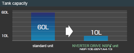
Greatly reduce the volume of hydraulic fluid
Low Nois
53db. of the wonder
The noise when dwelling is as quiet as a relaxing coffee shop.
The inverter drive saves energy and increases comfort at the same time.
(6MPa while maintaining pressure NSP-10E-22V1A4-20)
Specifications
| Power-supply voltage | 3Ø AC200 to 240V, 50/60Hz(200V Class) 3Ø AC380 to 480V, 50/60Hz(400V Class) |
| Rated input current | 9.7A/1.5kW, 13.4A/2.2kW(200V Class) 5.9A/1.5kW, 8.2A/2.2kW(400V Class) Note) In the 400V grade the input current value for the fan cooler is not included. |
| Pressure adjustment range | A2:1.5 to 4.0MPa A3:3.5 to 6.0MPa A4:5.5 to 8.0MPa |
| Discharge amount (no-load) | 0A* : 14L/min 1A* : 28L/min |
| HYDRAULIC OILs | Standard mineral-based hydraulic fluid (equivalent to ISO VG32) |
| OIL TEMPERATURE | Use at temperatures below 60°C. |
| Color | black (Semi-gloss) |
| ambient temperature / humidity | 0 to 35°C/20 to 80%RH (No condensation) (Keep the unit away from water-soluble cutting fluid mist. ) |
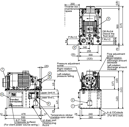
Mounting dimensions
| Type | Motor (kW-P) | Measurment | Approximate mass (kg) | ||||||||||
|---|---|---|---|---|---|---|---|---|---|---|---|---|---|
| LA | LB | LC | LD | LE | LF | LG | LH | LI | H | L | |||
| NSP-10E-15V*A*-21 | 1.5-4 | 510 | 5 | 501 | 265 | 236 | 164 | 119 | 172 | 30 | 10L | 8.5L | 48 |
| NSP-10E-22V1A*-21 | 2.2-4 | 540 | 35 | 521 | 256 | 174 | 129 | 55 | |||||
| NSP-20E-15V1A*-21 | 1.5-4 | 510 | 5 | 601 | 365 | 236 | 164 | 119 | 252 | 50 | 20L | 16L | 51 |
| NSP-20E-22V1A*-21 | 2.2-4 | 540 | 35 | 621 | 256 | 174 | 129 | 58 | |||||
·approximate mass, Does not include the hydraulic fluid
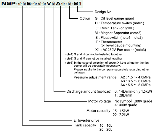
Explanation of model No
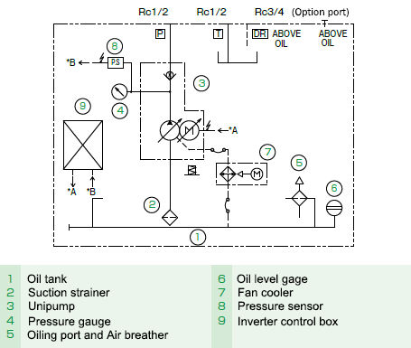
Hydraulic circuit diagram
Precautions for use
- Turning the inverter on and off by cutting the main power supply (circuit breaker) significantly reduces the life of the inverter and should be limited to once an hour or less. Contact us if you need to start and stop operations frequently.
- Do not change the inverter’s parameter settings.
- Use a 1/2 inch diameter two meter long flexible hose rated for maximum 14 MPa working pressure to connect the hydraulic unit’s P port (discharge port) and the external manifold (or actuator).
- Maximum peak pressure (set pressure + surge pressure) must be within 14 MPa. Install a relief valve on the hydraulic circuit side to cut surges if peak pressure is higher than 14 MPa.
- Volume of leakage on external hydraulic circuits must be less than 1 L/min. Consult us if leakage on the external hydraulic circuit is greater than 1 L/min.
- The volume of hydraulic fluid in the tank must stay within the range visible on the fluid level gauge (10L tank: approximately 1.5 L, 20L tank: approximately 4L).
Related Products
REQUEST QUOTATION

PAYMENT

LINK


