Japan, Nachi
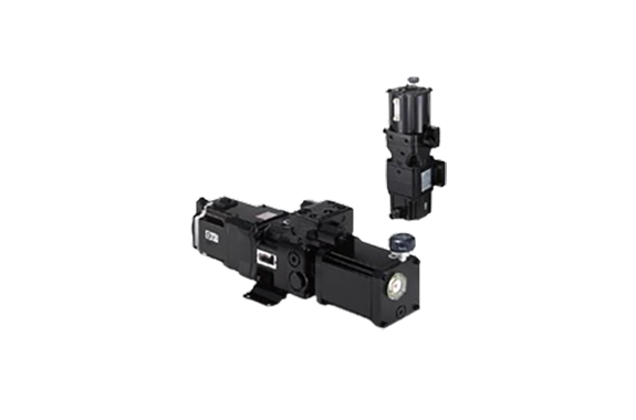
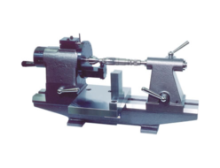
Nachi UPS Series Power Meister
Made in: Japan
Manufacturer: NACHI
Model: UPS Series
| Model | UPS-00A-2*07 | UPS-00A-2*10 | UPS-00A-3*10 | UPS-00A-2*15 | UPS-00A-3*15 | UPS-00A-4*15 | UPS-0A-2*12 |
| UPS-0A-4*12 | UPS-0A-2*20 | UPS-0A-4*20 | UPS-1A-5*35 | UPS-1A-7*35 | UPS-1A-9*35 | UPS-1A-11*35 | |
| UPS-1A-13*35 | UPS-1A-16*35 | UPS-1A-5*45 | UPS-1A-7*45 | UPS-1A-9*45 | UPS-1A-11*45 | UPS-1A-13*45 | |
| UPS-1A-16*45 | UPS-1A-7*55 | UPS-1A-9*55 | UPS-1A-11*55 | UPS-1A-13*55 | UPS-1A-16*55 | UPS-1A-9*75 | |
| UPS-1A-11*75 | UPS-1A-13*75 | UPS-1A-16*75 | UPS-1A-13*11K | UPS-1A-16*11K | UPS-00A-**07 | UPS-00A-**10 | |
| UPS-00A-**15 | UPS-0A-**12 | UPS-0A-**20 | UPS-1A-**35 | UPS-1A-**55 | UPS-1A-**75 | UPS-1A-**11K |
Features of UPS Series
- Strong power of Max, working pressure 30MPa
- Designed so pump operates only when necessary for energy savings and low noise.
- Realizes large energy savings compared to conventional hydraulic systems.
- High-speed processing of the servo controller makes positioning on the order of µm possible.
- Compact all-in-one design saves space.
(It is possible to select either vertical or horizontal setup)
A compact hydraulic system that realizes large energy savings and high precision
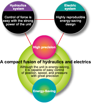
- The AC servo motor controls hydraulic pump rotation speed and direction.
- It is possible to generate pressure and flow to match the operating cycle of machinery and to stop during idle times.
- Leads to large energy savings by operating the pump only when necessary.
- Position, speed, and pressure are controlled with great precision by using a high-speed digital processing servo controller.
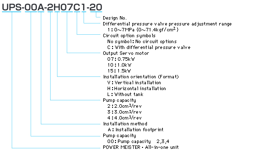
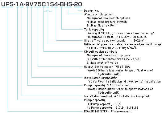
Hydraulic Units Explanation of model No.
UPS-00A
UPS-0A/UPS-1A
Specifications
Specifications Hydraulic Units
| Electricmotor | AC Servo motor (0.75 Power-supply voltage Three-Phase (Servo amplifier Voltage) Need fan motor power supply only 11kW single-phase AC200 |
|---|---|
| Pump | Piston Pump (2.0 |
| Using ambient temperature/humidity | 0 |
| Allowable temperature range of the hydraulic oil | 5 |
| Recommended hydraulic oils | Wear resistant hydraulic fluid ISO VG32 to 68 (VG46 recommended) |
| Working viscosity range | 20 |
| Oil contamination degree | NAS 10 Class or less |
| SAFETY VALVE adjustment of pressure Adjustment range of pressure | UPS-00A : 3.5 UPS-0A/1A : 3.5 |
| Maximum pressure | 30Mpa (hydraulic pump part) (Maximum operating output varies according to the combination of motor performance and options) |
| Color | black |
UPS-00A
| Type | Output motor kW | Pump capacity cm3rev | Maximum RPM min-1 (note1) | Maximum Flow l/min (note2) | Rated pressure MPa (Continuous) (note3) | Maximum pressure MPa (Short time) (note3) | Tank capacity Lit. (nominal) | Allowed hydraulic fluid level range Lit. (Estimate) (note4) |
|---|---|---|---|---|---|---|---|---|
| UPS-00A-2*07 | 0.75 | 2.0 | 3000 | 6.0 | 6.4 | 9.6 | V:0.75 H:0.65 L:Without tank (note5) | V:0.3 H:0.2 |
| UPS-00A-2*10 UPS-00A-3*10 | 1.0 | 2.0 3.0 | 3000 | 6.0 9.0 | 8.5 5.7 | 12.7 8.5 | ||
| UPS-00A-2*15 UPS-00A-3*15 UPS-00A-4*15 | 1.5 | 2.0 3.0 4.0 | 3000 | 6.0 9.0 12.0 | 19.2 12.8 9.6 | 28.8 19.2 14.4 |
UPS-0A
| Type | Output motor kW | Pump capacity cm3rev | Maximum RPM min-1 (note1) | Maximum Flow l/min (note2) | Rated pressure MPa (Continuous) (note3) | Maximum pressure MPa (Short time) (note3) | Tank capacity Lit. (nominal) | Allowed hydraulic fluid level range Lit. (Estimate) (note4) |
|---|---|---|---|---|---|---|---|---|
| UPS-0A-2*12 UPS-0A-4*12 | 1.2 | 2.0 4.0 | 3000 | 6.0 12.0 | 15.2 7.6 | 22.8 11.4 | V:1.9 H:1.5 | V:0.6 H:0.3 |
| UPS-0A-2*20 UPS-0A-4*20 | 2.0 | 2.0 4.0 | 3000 | 6.0 12.0 | 25.4 12.7 | 30.0 19.0 |
UPS-1A
| Type | Output motor kW | Pump capacity cm3rev | Maximum RPM min-1 (note1) | Maximum Flow l/min (note2) | Rated pressure MPa (Continuous) (note3) | Maximum pressure MPa (Short time) (note3) | Tank capacity Lit. (nominal) | Allowed hydraulic fluid level range Lit. (Estimate) (note4) |
|---|---|---|---|---|---|---|---|---|
| UPS-1A-5*35 UPS-1A-7*35 UPS-1A-9*35 UPS-1A-11*35 UPS-1A-13*35 UPS-1A-16*35 | 3.5 | 4.7 6.7 9.0 11.0 12.9 15.8 | 2500 | 11.8 16.8 22.5 27.5 32.3 39.5 | 21.1 14.8 11.7 9.6 8.2 6.7 | 30.0 22.2 17.5 14.3 12.2 10.0 | No symbol: 4.5 A:3.0 B:6.0 | Tank capacity:No symbol V:1.2, H:0.6Tank capacity:A V:0.6, H:0.4Tank capacity:B V:2.8, H:0.8 |
| UPS-1A-5*45 UPS-1A-7*45 UPS-1A-9*45 UPS-1A-11*45 UPS-1A-13*45 UPS-1A-16*45 | 4.5 | 4.7 6.7 9.0 11.0 12.9 15.8 | 2500 | 11.8 16.8 22.5 27.5 32.3 39.5 | 30.0 22.6 17.8 14.6 12.4 10.2 | 30.0 30.0 26.8 21.9 18.7 15.2 | ||
| UPS-1A-7*55 UPS-1A-9*55 UPS-1A-11*55 UPS-1A-13*55 UPS-1A-16*55 | 5.5 | 6.7 9.0 11.0 12.9 15.8 | 2500 | 16.8 22.5 27.5 32.3 39.5 | 27.9 22.0 18.0 15.3 12.5 | 30.0 30.0 27.0 23.0 18.8 | ||
| UPS-1A-9*75 UPS-1A-11*75 UPS-1A-13*75 UPS-1A-16*75 | 7.5 | 9.0 11.0 12.9 15.8 | 2500 | 22.5 27.5 32.3 39.5 | 30.0 24.7 21.0 17.2 | 30.0 30.0 30.0 25.8 | ||
| UPS-1A-13*11K UPS-1A-16*11K | 11.0 | 12.9 15.8 | 2500 | 32.3 39.5 | 30.0 25.1 | 30.0 30.0 |
(note1)Operating pressure may be limited by maximum RPM depending on the motor output
(note2)This is the theoretical flow under no load. The actual flow will vary depending on the load pressure.
(note3)Rated pressure is (available) pressure at the rated torque of the motor, and maximum operating pressure is pressure output at 150% torque. However, if this pressure exceeds 30MPa, the maximum operating pressure of the hydraulic unit is limited to below 30MPa.
(note4)An auxiliary tank can be connected if fluctuation in oil volume is greater than allowed values. Contact us for information.
(note5)An oil tank will be separately necessary. Our company can make the oil tanks so contact us for information if you need one.
(note6)Operating conditions may limit the maximum RPM and operating pressure to values lower than those shown in the table above, contact us for more information.
Contact us about operations in which pressure is continuously added over a long period of time because the temperature of the hydraulic fluid sometimes rises due to the operating pressure, so restrictions on the operating pressure and the additional installation of a refrigeration system may be necessary.
(note7)The operating hydraulic fluid temperature is affected by a variety of factors such as the hydraulic unit installation environment, operational method, load condition, etc. so be sure to confirm with your customer in a situation in which the production machine is operating.
In the case that the hydraulic fluid temperature exceeds the operational hydraulic fluid temperature range, it will be necessary to additionally install a separate refrigeration system, so contact us for information.
Specification Servo controller
Type: EPD-PD3-10-D2-20
| Power-supply voltage/Power consumption | DC24V±15% / 10W or less | Separate power supply for sensor is needed | |
|---|---|---|---|
| Ambient temperature/Humidity | 0 | ||
| Control Content | Cylinder position velocity pressure control | Control mode automatic switching function available | |
| Command Input | Speed Command | Analog voltage DC±10V/Maximum cylinder speed(*1), Cylinder extended by positive voltage, cylinder retracted by negative voltage | (*1)Set using parameters |
| Pressure Command | Analog voltage DC±10V/Maximum control pressure(*2) Positive voltage adds pressure to head side, negative voltage adds pressure to rod side | (*2)Set using trimmers | |
| Position Command | Position selection contact signal (4 contacts), target position selected by bit pattern of 4 contacts, the accelerated and decelerated movement function up until the target position inside the controller is generated and moved, and position of the cylinder is maintained | Target position, maximum movement speed, acceleration and deceleration speed set in advance using internal parameters | |
| Input signal(Contact signal) | Servo on, alarm reset, control mode external switching signal, start point search start signal, start point retraction end point LS, start point proximity LS | ||
| Output signal | Alarm, servo ready, control mode monitor, start point search end/in position (also output), pressure consistency | ||
| Input preassure Sensor | Analog voltage0.5 | Uses pressure sensor with response time of 1ms or less. | |
| Input position sensor | 90° phase difference biphasic pulse, start point pulse (line receiver input) or analog voltage 0 to 10V | If using pulse output positioning sensor, a start point search is necessary once after turning on the power. Pulse output positioning sensor: Uses sensor with resolution of 1µm or less Analog voltage output positioning sensor: Uses sensor with response time of 2ms or less | |
| Servo amplifier I/F | Output: Motor revolve command (analog voltage ±10VDC), Servo ON,Reset Servo Ararm Input:Servo Ararm,Servo Ready | ||
| Control panel | Signed 5-digit display, 4 key input, selector switch | Data setting and display, trial operation function | |
- The connector for controller and the pins are attached.
- If you use a spacer for the servo controller (option: FZV-8676-02A-01), the installation dimensions will be the same as for the former design [EPD-PD2-10(-A)-D2-10], and the height of the connector from the installation surface will be almost the same.
Servo amplifier specification
| Hydraulic Units type (UPS series) | Output motor kW | corresponding servo amplifier type | Remarks |
|---|---|---|---|
| UPS-00A-**07 | 0.75 | EPA-PD1-10R075-20 | |
| UPS-00A-**10 | 1.0 | EPA-PD1-10R100-20 | |
| UPS-00A-**15 | 1.5 | EPA-PD1-10R150-20 | |
| UPS-0A-**12 | 1.2 | EPA-PD1-10R120-20 | |
| UPS-0A-**20 | 2.0 | EPA-PD1-10R200-20 | |
| UPS-1A-**35 | 3.5 | EPA-PD1-10R350-20 | |
| UPS-1A-**45 | 4.5 | EPA-PD1-10R450-20 | |
| UPS-1A-**55 | 5.5 | EPA-PD1-10R550-20 | |
| UPS-1A-**75 | 7.5 | EPA-PD1-10R750-20 | |
| UPS-1A-**11K | 11.0 | EPA-PD1-10R11K-20 |
(note1) Operating power source :THREE-PHASE AC200![]() 220V 50/60Hz
220V 50/60Hz
(note2) Separate motor cable and encoder cable are needed to connect the servo motor installed on the hydraulic unit.
(note3) An external regenerative resistor may need to be added in some operating conditions if the capacity of the built-in or external regenerative resistor is not sufficient. For more details contact us with information about your operating conditions (attach the load motion diagram).
(note4) Cable connector included.
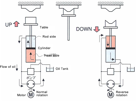
Working principle
Rotating the motor forward brings hydraulic fluid to the head side of the cylinder which pushes the cylinder down. The direction the pump rotates controls the direction of the cylinder, and the speed of rotation controls the speed.
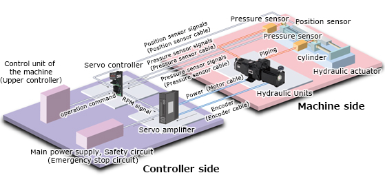
System configuration (Standard configuration)
System performance
Pressure characteristics | Velocity characteristics |
Pressure sine wave response | Velocity sine wave response |
| Power consumption comparison | |
 | |
Application examples and effects
| Bending machine | More compact machines and improved precision of processing dimensions |
| Caulking machine, Press machine | These units are able to control swaging (pressured insertion) capability and control the swaging (pressured insertion) completion position so quality management is easy. A positioning mechanism using a conventional mechanical stopper is unnecessary, liberating you from variations in results due to workers. |
| Grinding machine | Improves the precision of the positioning of the grinding commencement position, having a large energy-saving effect when continuously pressurizing over a long period of time using a fixed pressure. |
| Precision Press | Improves product quality by smoothly switching from high-speed movement to pressurization control without any surge. Cycle time is shortened. |
| Straightening machine | It achieves energy-saving, low noise, and a reduction in the amount of hydraulic fluid. Space is saved and transportation and packaging costs are reduced by installing a hydraulic unit in the machine. |
| Other | A full range of hydraulic systems for machines which are required to be more compact, machines which require a high thrust that cannot be obtained with ball screws, etc. |
Related Products
REQUEST QUOTATION

PAYMENT

LINK


