Nissan Tanaka
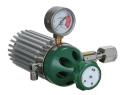
NISSAN TANAKA S Series Analytical Pressure Regulators

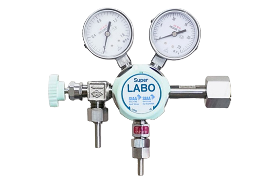
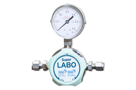
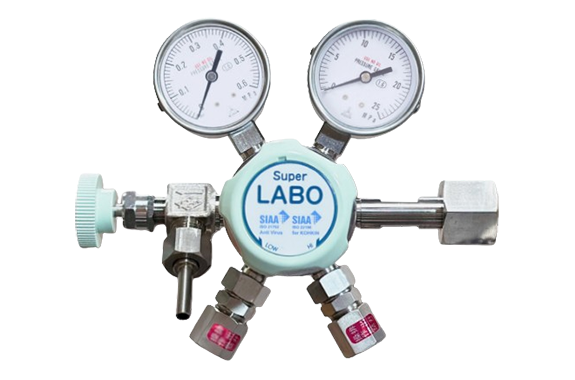
Manufacturer: Nissan Tanaka
Model: S Series (S1, SL, S2)
S/LABO S series (antibacterial/antiviral handle)
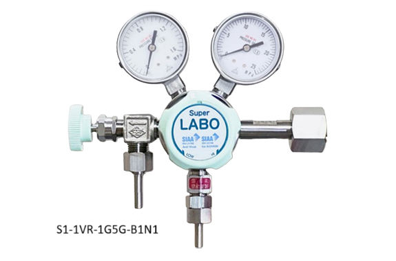
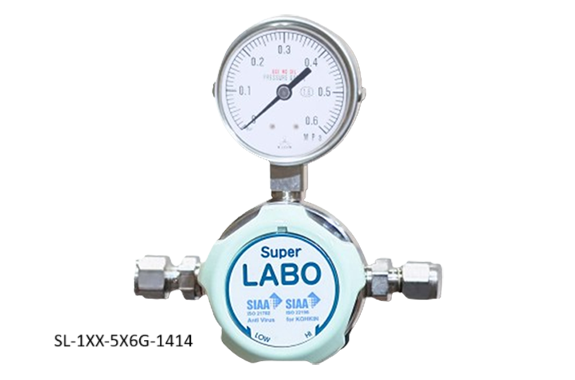
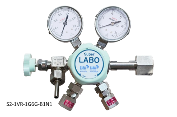
The industry’s first antibacterial and antiviral handle adjuster.
Choose hygienic equipment for places where hygiene is a concern! Pressure regulator for analysis and high-purity gas Super LABO series.
Features
- The handle undergoes antibacterial and antiviral treatment, showing consideration not only for performance but also for hygiene.
- In addition to being made of stainless steel, you can choose from various O-ring materials, making it suitable for a wide range of gas types.
- SUS316L metal diaphragm is used to reduce external leakage and maintain purity.
- Produced in a clean area for purity maintenance.
- Fluorine-based grease that can be used even in a vacuum is used in the valve for purity maintenance.
- A filter is built into the inlet side to prevent backflow.
Specifications
| Model | S1 | SL | S2 | |
|---|---|---|---|---|
| Construction | primary high-pressure use | primary high-pressure use | two-stage pressure reduction | |
| Main Material of Gas Contact Parts | Main body/ SUS316L, Diaphragm/ SUS316L Others/ SUS316・Fluororesin | |||
| Usage Pressure Range | InletSide※1(P1) | 1.5~15 | with exhaust valve: 0.05~1 | 1.5~15 |
| without exhaust valve: 0.05~5 | ||||
| Outlet Side(P2) | 0.25MPa gauge : 0.02 ~ 0.15 | |||
| 0.6MPa gauge : 0.02 ~ 0.4 | ||||
| 1.0MPa gauge : 0.02 ~ 0.6 | ||||
| 1.6MPa gauge※2: 0.02 ~ 1.0 | ||||
| Operating temperature [℃] | -10 ~40※3 | |||
| Weight [kg] | approximately 1.6 (S1-1VR-1G5G-B1N1) | approximately 1.5 (SL-1XX-5X6G-1414) | approximately 2.1 (S2-1VR-1G8G-B1N1) | |
| Flow Rate※4 [L/min(nor)] Nitrogen Gas | 250 P1=10PMa P2=1MPa | 260 P1=1MPa P2=0.6MPa | 200 P1=8MPa P3=0.6MPa | |
※1 When an inlet pressure gauge is installed, it determines the maximum operating pressure on the inlet side based on its range.
※2 The S2 series does not allow the selection of a 1.6MPa gauge for the outlet pressure.
※3 The accuracy of the pressure gauge is equivalent to JIS Class 1.6 within the temperature range of -5 to 40°C.
※4 If the usage flow rate is 0.2 L/min(nor) (equal to 200 ml/min(nor)) or less, please use S2 or SL.
Product Name and Configuration
The S/LABO product name consists of the symbols in the table below. Please configure the product name according to your required specifications.
We will consider whether or not we can accommodate specifications not listed in the table below as a special order. Please contact us.


| Symbol | Specifications |
| ① | Main Body |
|---|---|
| 1 | Primary side high-pressure use |
| L | Primary side high-pressure use |
| 2 | Two-stage pressure reduction |
| ② | O-ring Material (refer to the selection table on the right) |
| V | FKM (Viton) |
| E | EPDM |
| N | CR (Neoprene) |
| X | Without O-ring |
| ③ | Exhaust Valve |
| R | with exhaust valve |
| X | none (no exhaust valve port) |
| ④ | Inlet Pressure Gauge Maximum Scale | |
|---|---|---|
| 1 | S1. S2 | 25MPa |
| 2 | 16MPa | |
| 3 | SL | 5.0MPa |
| 4 | 2.5MPa | |
| 5 | 1.6MPa | |
| 6 | 1.0MPa | |
| 7 | 0.6MPa | |
| 8 | 0.25MPa | |
| ⑤ | Inlet Pressure Gauge※1 |
|---|---|
| G | with pressure gauge |
| C | with linked gauge※2 |
| X | none (no pressure gauge port) |
| ⑥ | Outlet Pressure Gauge Maximum Scale |
| 5 | 1.6MPa |
| 6 | 1.0MPa |
| 7 | 0.6MPa |
| 8 | 0.25MPa |
| ⑦ | Outlet Pressure Gauge |
| G | with pressure gauge |
| C | with linked gauge※2 |
| ⑧ | Inlet Connection | |
|---|---|---|
| No PV | With PV | Form |
| B1 | P1 | W22-14 right female |
| B2 | P2 | W22-14 left female |
| B3 | P3 | W26-14 right female |
| B6 | 20.9-14 left female | |
| 10 | NPT1/4 female | |
| 13 | 1/8-inch swage lock | |
| 14 | 1/4-inch swage lock | |
| 16 | 6mm swage lock | |
| 17 | 1/4″ VCR male | |
| 18 | 1/4″ VCR female | |
| 19 | Rc1/4 (adapter) | |
| 1A | 3/8-inch swage lock | |
| ⑨ | Outlet Connection | |
|---|---|---|
| No NV | With NV | Form |
| 10 | N0 | NPT1/4 female |
| 11 | N1 | M16×1.5 right male |
| 12 | N2 | M16×1.5 left male |
| 13 | N3 | 1/8-inch swage lock |
| 14 | N4 | 1/4-inch swage loc |
| 16 | N6 | 6mm swage lock |
| 17 | N7 | 1/4-inch VCR male |
| 18 | N8 | 1/4-inch VCR female |
| 19 | N9 | Rc1/4 (adapter) |
| 1A | NA | 3/8-inch swage lock |
| ⑩ | Flowmeter (optional) | |||
|---|---|---|---|---|
| Symbol | Used gas | Range (L/min(nor)) | Setting pressure | Outlet configuration |
| F80 | Ar | 0.05~0.5(※4) | 0.1 | M16X1.5R |
| F81 | 0.1~1 | |||
| F82 | 0.5~5 | |||
| F82MY | 1.5~15 | 0.2 | ||
| ※3 | 2.5~25 | |||
| F83 | NH3 | 0.05~0.5(※4) | 0.1 | |
| F84 | 0.1~1 | |||
| F85 | 0.5~5 | |||
| ※3 | O2 | 1~10 | 0.1 | |
| ※3 | 2.5~25 | 0.2 | ||
| F86 | H2 | 0.1~1 | 0.1 | M16X1.5L |
| F87 | 0.5~5 | |||
| F88 | 1~10 | |||
| ※3 | 2.5~25 | |||
| F89 | N2 | 0.05~0.5(※4) | 0.1 | M16X1.5R |
| F90 | 0.1~1 | |||
| F91 | 0.5~5 | |||
| F91D | 1~10 | |||
| F91LS | 2.5~25 | 0.2 | ||
| F92 | SO2 | 0.05~0.5(※4) | 0.1 | |
| F93 | 0.1~1 | |||
| F94 | 0.5~5 | |||
| F95 | He | 0.3~3 | 0.1 | |
| F96 | 1~10 | |||
| F97 | H2S | 0.1~1 | 0.1 | M16X1.5L |
| F98 | 0.5~5 | |||
※3 This is a new design. Please inquire.
※4 The displayed flow rate on the product will be in the range of 50 to 500 ml/min(nor).
| ⑪ | Additional Specifications Optional |
| 00 | Helium leak test performed (※5) |
| 02 | for nitrous oxide gas |
| 03 | for hydrogen sulfide gas |
| 31 | pressure gauge elbow facing inward (※6) |
| 52 | for sulfur hexafluoride and some Freon gases (※6) |
| 120 | carbon dioxide gas mitigation sheet (※7) |
※5 It is necessary to couple the outlet-side pressure gauge with a differential pressure gauge※2.
※6 Only in the case of SL.
※7 We recommend it for cases where valve opening and closing are performed frequently, such as in incubators.
Attention
※1 Pressure gauges with a full scale of 2.5MPa or higher cannot be coupled. Also, if you select ‘1: One-stage high-pressure use’ or ‘2: Two-stage pressure reduction type’ in (①), you cannot select ‘X: None (no pressure gauge port)’.
※2 When converting the pressure gauge to a differential pressure gauge, the dial color will be ‘blue.’ (In the case of a combination of a differential pressure gauge and a positive pressure gauge, the positive pressure gauge will also have a blue dial)
- PV stands for Purge Valve, and NV stands for Needle Valve.
- The mixing valve with a flowmeter has a needle valve attached to the outlet of the flowmeter, so please select the symbol with NV付 (Needle Valve included).
- When the outlet fitting is M16×1.5, it comes with a nut and two types of hose connectors (1/4″ pipe shape and JIS No. 2 shape) included.
O-ring Symbol Selection Table by Gas Type
Chemical formula (molecular weight) | E (EPDM) | N (CR) | V (FKM) Standard |
|---|---|---|---|
| N2O (44.01) | ⚫1,3 | ||
| C2H2 (26.04) | ⚫ | ||
| Ar (39.95) | ⚫ | ||
| NH3 (17.03) | ⚫ | ||
| CO (28.01) | ⚫ | ||
| NO (30.01) | ⚫ | ||
| C2H6 (30.07) | ⚫ | ||
| C2H4 (28.05) | ⚫1 | ||
| C2H5Cl (54.52) | ⚫ | ||
| HCl (36.47) | Please use the M series | ||
| CH2=CHCl (62.50) | ⚫ | ||
| CH3Cl (50.49) | ⚫ | ||
| Cl2 (70.91) | Please use the M series | ||
| Xe (131.29) | ⚫ | ||
| Air (28.97) | ⚫ | ||
| Kr (83.80) | ⚫ | ||
| C2H4O (44.05) | ⚫ | ||
| O2 (32.00) | ⚫ | ||
| C3H6 (42.08) | ⚫ | ||
| C2H5Br (108.97) | ⚫2 | ||
| HBr (90.91) | Please use the M series | ||
| CH3Br (94.94) | ⚫2 | ||
| H2 (2.02) | ⚫ | ||
| N2 (28.01) | ⚫ | ||
| SO2 (64.06) | ⚫1,3 | ||
| CO2 (44.01) | ⚫ | ||
| N2O4(NO2) (46.01) | ⚫ | ||
| Ne (20.18) | ⚫ | ||
| CH2=CHCH=CH2 (54.09) | ⚫ | ||
| CH(CH3)3 (58.12) | ⚫ | ||
| CH3(CH2)2CH3 (58.12) | ⚫ | ||
| CH3CH2CH=CH2 (56.11) | ⚫ | ||
| CH2=C=CH2 (40.07) | ⚫ | ||
| C3H8 (44.01) | ⚫ | ||
| CH2=CHCH3 (42.08) | ⚫ | ||
| CCl3F (137.40) | ⚫ | ||
| CCl2F2 (120.90) | ⚫ | ||
| CClF3 (104.46) | ⚫ | ||
| CBrF3 (148.91) | ⚫ | ||
| CH3CHO (44.10) | ⚫ | ||
| CH3SH (48.10) | ⚫ | ||
| CH3OCH3 (46.10) | ⚫ | ||
| CH3NH2 (31.10) | ⚫ | ||
| CF4 (88.00) | ⚫1 | ||
| CHCl2F (102.92) | ⚫ | ||
| CHClF2 (86.48) | ⚫ | ||
| CHF3 (70.01) | ⚫ | ||
| C6H14 (86.20) | ⚫ | ||
| C6H12 (84.16) | ⚫ | ||
| He (4.00) | ⚫ | ||
| CH3(CH2)2CH3 (72.15) | ⚫ | ||
| CH4 (16.04) | ⚫1 | ||
| CH3C=CH (40.06) | ⚫ | ||
| COS (60.07) | ⚫ | ||
| H2S (34.08) | ⚫3 | ||
| SF6 (146.05) | ⚫3 | ||
Accessories
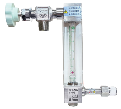
Flowmeter
It is designed specifically for the S-LABO series and is assembled in a clean area. This flowmeter is specially designed for use with the S-LABO series.
Purge valve
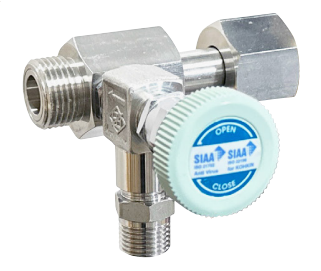
This is a purge valve used to exhaust any residual toxic or corrosive gases from the regulator when it is removed from the cylinder after use.
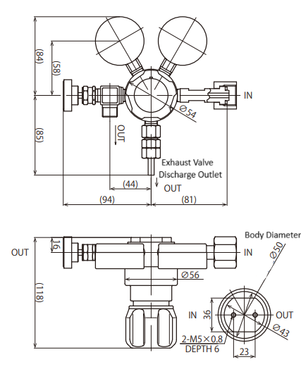
Exterior Diagram
S1ー1VRー□G□GーB1N1
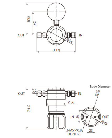
 SLー1XXー5X□Gー1414
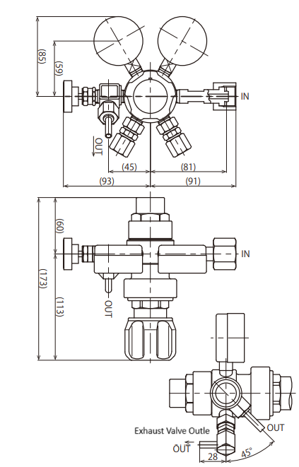
S2ー1VRー1G□GーB1N1
Kouei is Distributor/Agent of Nissan Tanaka
Other items of Nissan Tanaka
Request the quotation for Nissan Tanaka

