Japan, Orientalmotor
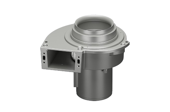
Orientalmotor MB Series S Type AC Centrifugal Blowers (Sirocco fans)
Made in Japan
Manufacturer: ORIENTAL MOTOR CO., LTD.
Model: MB Series S Type
Rapidly Cool Load – Forced Cooling After Heat Processing

The MB Series S type is characterized by a faster exhaust wind speed than a standard axial flow fan.
When air-cooling a load, the faster the wind speed, the less time it takes to cool. Ideal for spot cooling during heat processing.
Example) When cooling a 300 °C steel plate (200 mm × 200 mm × 10 mm) to 100 °C
| Axial Flow Fan of Equivalent Size | MB Series S type impeller diameter φ120 mm | |
|---|---|---|
| Cooling Time* | 5 minutes 30 seconds | 2 minutes 30 seconds |
| Wind Speed | 6.7 m/s | 19.2 m/s |
*Operating ambient temperature is calculated at an intake air temperature of 25 °C.
If cooling time can be shortened, wait time for post-process will be reduced.
Using a centrifugal blower in the cooling system improves overall process efficiency and productivity.
Exhausting Air Through Ducts – Exhaust Inside Laboratory Equipment (Supports intake air temperatures of -10 °C to +90 °C or lower)

The MB Series S type is ideal for duct ventilation because it is designed so that a duct can be directly attached to the intake.
Supports Intake Air Temperatures From -10 °C min. to +90 °C max.
Intake air temperatures from -10 °C min. to +90 °C max. are supported so that warm air flow from dryers and heating equipment can be expelled as exhaust.
Also, please confirm the following operating ambient temperature when blowing high temperature air.
| Intake Air Temperature | Operating Ambient Temperature* |
|---|---|
| -10 °C min. to +50 °C max. | -10 °C~+50 °C (non-freezing) |
| Over +50 °C to +90 °C max. | -10 °C~+40 °C (non-freezing) |
- *Cannot be used in a temperature-controlled environment at -10 °C max., such as in a freezer.
Improved Duct Installation
The intake is stepped to allow direct duct installation.
If you install a duct joint (sold separately), you can also attach a duct to the exhaust outlet.

Blowing Liquids and Dust – Air Blow (Coating of liquid food products)

The MB series S type is ideal for blow-off applications because it sends out a highly directional wind with a large static pressure.
Blowing with wind power means there is no need to touch the load directly when adjusting the amount of liquid or powder.
Achieves uniform blow-off while keeping the load clean.
Manually Adjusting Blow-Off Amount

Manual air flow adjustment is possible by installing an air flow adjustment damper (sold separately).
You can adjust the air flow according to the load while looking at the scale. Refer to here for more details on how to adjust air flow.
Adsorb Lightweight and Flat Loads – Suction of Printed Paper (Tidying up)

The MB Series S type is ideal for applications where air is sucked in with significant static pressure to adsorb the load.
When transporting lightweight and flat loads, it prevents load scattering and position errors, and improves in-process defects such as machining errors and loss.

Selectable Mounting Method/Manual Air Flow Adjustment
Use Mounting Holes and Mounting Brackets to Install According to Application

Intake Side Installation

Exhaust Outlet Side Installation

Mounting pedestal

Mounting Bracket for Exhaust Outlet
The MB Series S type allows you to change the position of the exhaust outlet and the direction in which the lead wire is pulled out.
Remove motor assembly screws and rotate motor in 90˚ increments to adjust its orientation.

Intake Side Installation (Through hole)
The through hole on the body can be used for direct installation from the centrifugal blower side.
Exhaust Outlet Side Installation (Tapped hole)
The tapped holes on the body can be used for direct installation from the equipment side.
Mounting Pedestal
By assembling the mounting pedestal (sold separately) to the centrifugal blower, it can be mounted vertically to the ground.


Mounting Bracket for Exhaust Outlets (Only for impeller diameter φ120 mm)
By attaching the mounting brackets for exhaust outlets (sold separately) to the centrifugal blower, it can be mounted from the blower side.

Air Flow Can be Adjusted Easily, Manually, and on the Spot
Manual air flow adjustment is possible by installing an air flow adjustment damper (sold separately).

Adjust the opening area of the intake to change the air flow. Adjustment can be performed manually.


A scale is marked on the body of the air flow adjustment damper.
A graph (reference value) of changes in scale and air flow is posted on the product details page of the air flow adjustment damper.
From the “Filter by Specs” page, select the name of the product you wish to check the specifications of from the following table.
Structure and features of centrifugal blower
The Centrifugal Blower is a Cooling Fan That Sends Out a Directed Wind With High Static Pressure
Structure of Centrifugal Blowers (Sirocco fans)
Impellers (forward-facing blades) are arranged in a cylindrical shape inside the centrifugal blower.
The centrifugal force created by rotating the impeller with a motor generates a swirling flow almost perpendicular to the axis of rotation. The swirling flow is rectified in 1 direction by a casing called a scroll, increasing the pressure. This restricts the exhaust outlet and concentrates the wind to be sent out in a specific direction.

Differences From Axial Flow Fans
We compare the features of the centrifugal blower with axial flow fans that are used to cool and ventilate the inside of equipment.
| Product Line | Axial Flow Fans | Centrifugal Blowers (Sirocco fans) |
|---|---|---|
| External View |  | 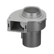 |
| Features | Large capacity air flow | High static pressure and highly directional air flow |
| Characteristics |
|
|
| Application |
|
|
As the characteristics of each offer differing advantage, usage according to application is the crucial point.
Refer to here for more about the features of axial flow fans.
Product Line
MB Series S Type
| Size | Power Supply Voltage | Maximum Air Flow [m3/min] | Maximum Static Pressure [Pa] |
|---|---|---|---|
Impeller Diameter φ100 mm | Three-Phase 200 VAC, Three-Phase 220/230 VAC Single-Phase 100 VAC Single-Phase 110/115 VAC Single-Phase 200 VAC Single-Phase 220/230 VAC | 2.5 | 320 |
Impeller Diameter φ120 mm | 5.2 | 450 |
Series List of Centrifugal Blowers (Sirocco fans)
For products other than impeller diameter φ100 mm and φ120 mm, please select the following series. DC input type and variable speed type are also available.
| Series | Power Supply Voltage | Impeller Diameter | |||||
|---|---|---|---|---|---|---|---|
| φ50 mm | φ60 mm | φ80 mm | φ100 mm | φ120 mm | φ160 mm | ||
| MB Series S Type | AC | – | – | – | ● | ● | – |
| MB Series | AC | ● | ● | ● | ● | ● | ● |
| MB Series Variable Speed Type Fans | AC | – | – | – | ● | – | – |
| MBD Series | DC | – | – | ● | ● | ● | – |
Related Products
-

Vessel No.GT-3900VP Air Impact Wrench Super Light V-Hammer
-
Furuto Industrial (Monf) No.8003 Quiet Cloth Tape
-
Vessel No.GT-P14JL Air Long Impact Wrench Single Hammer
-
SAKUSAKU SF-53M-D Carbide Rotary Burr Three Radius End Shape
-
SAKUSAKU 4SS-20D 9.0S Carbide Square End Mill 4-Flute
-
Nippon KSA Steel Plate Finish Surface Roughness Standard Plate
REQUEST QUOTATION

PAYMENT

LINK


