- Home
- Products
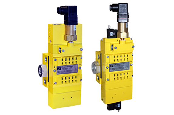
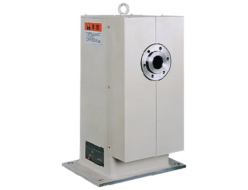
- Ross Asia CrossMirror CM26 series double valve Safety cat. 4 PL e, internal monitoring, manual reset
Japan, Ross Asia
Ross Asia CrossMirror CM26 series double valve Safety cat. 4 PL e, internal monitoring, manual reset
Made in Japan
Manufacturer : Ross Asia
Model : CrossMirror CM26 series double valve
Control Reliable CroSS Mirror® Double Valves CM26 Series Product Overview
Safe Return Safety Function
This valve is constructed with precision, stainless steel spools as the main valve elements, and is designed to offer added safety to the operation of many pneumatically controlled machines such as small size pneumatic cylinder-operated presses, valve operators, and safety latches.
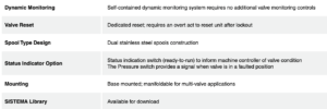
The valve has a self-contained monitoring system, requires no additional monitoring and is designed for Category 4, Performance Level e applications. Upon detecting a fault due to discordant spool valve action, the valve locks out and remains so until an overt reset signal (electrical solenoid or remote pneumatic) is applied. This prevents unintentional reset and further bolsters safety. The optional pressure switch provides valuable feedback to the operator regarding whether or not the valve is in “ready-to-run” condition.
VALVE FEATURES’
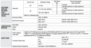
PRODUCT CREDENTIALS

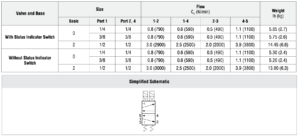
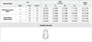
Specifications

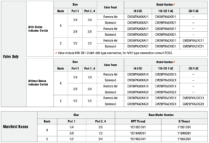
Ordering Information
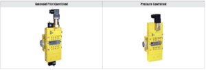
5/2 SOLENOID PILOT CONTROLLED VALVES – VALVE AND BASE ASSEMBLY
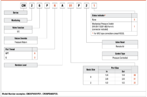
MODEL NUMBER CONFIGURATOR(4-Way 2-Position Valves)

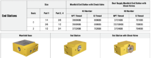
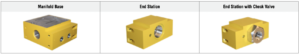
5/2 Solenoid Pilot Controlled Valves – Valves, Manifold Bases, and End Stations for Manifold Assemblies
In addition to the manifold, an end station kit with a check valve must be ordered for each assembly. The number of manifolds with a single supply inlet will be limited to the pressure and flow rate of the system. Too many manifolds may result in too large of an internal pressure drop resulting in valve faults. The manifold end station kit with dual inlet check will allow the manifold to be supplied with air from both ends of the assembly.
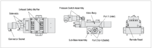
Valve Operation
| SOLENOID PILOT CONTROLLED VALVES | |
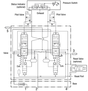
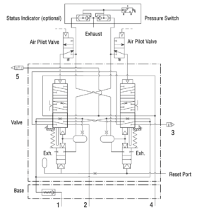
| Normal Operation | The valve is operated by energizing both pilot solenoids simultaneously. This causes both main valve elements to be actuated so that air from inlet port 1 flows to outlet port 4, but not to port 2. Air downstream of port 2 is exhausted through port 3. When the solenoids are de-energized, both valve elements are de-actuated, and air then flows from inlet port 1 to outlet port 2, but no longer to outlet port 4. Air downstream of port 4 is exhausted through port 5. On first operation, or after repair, the pilot valve supply circuit and inherent monitoring elements may need to be reset. |
| Valve Locked-out | Whenever the valve elements operate in a sufficiently asynchronous manner, either on actuation or de actuation, the valve will move to a locked-out position. In the locked-out position, one crossover and its related timing chamber will be exhausted, and the other crossover and its related timing chamber will be fully pressurized. The valve element (side B) that is partially actuated has pilot air available to fully actuate it, but no air pressure on the return piston to fully de-actuate the valve element. The return springs are limited in travel, and can only return the valve elements to the intermediate (locked-out) position. Sufficient air pressure acting on the return pistons is needed to return the valve elements to a fully home position. |
| Detecting a Malfunction | If the main valve elements are not both actuated or de-actuated synchronously, the valve defaults to the locked-out position so that outlet port 2 receives full inlet pressure, and outlet port 4 is exhausted through port 5. The valve must now be “reset” to resume normal operation. |
| Resetting the Valve | The valve will remain in the locked-out position, even if the inlet air supply is removed and re-applied. A remote reset signal must be applied to reset the valve. Reset is accomplished by momentarily pressurizing the reset port. Actuation of the reset piston physically pushes the main valve elements to their home position. Actuation of the reset piston also opens the reset poppet, thereby, immediately exhausting pilot supply air, thus, preventing valve operation during reset. De-actuation of reset pistons causes the reset poppets to close and pilot supply timing chambers to fully pressurize. Reset pressure can be applied by a remote 3/2 normally closed valve, or from an optional 3/2 normally closed solenoid (which includes an integral manual reset button) mounted on the reset adapter. |
| Status Indicator | The optional status indicator pressure switch will actuate when the main valve is operating normally, and will de-actuate when the main valve is in the locked-out position or inlet pressure is removed. This device is not part of the valve lockout function, but, rather, only reports the status of the main valve. |
| Valve Schematic | |
 |
| Solenoid & Pressure Switch Pinouts | |
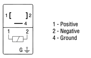
| Solenoid | DIN EN 175301-803 Form A |
 | |
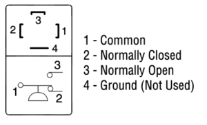
| DIN EN 175301-803 Form C | |
 | |
| DIN EN 175301-803 Form A | |
 | |
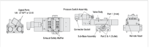
Solenoid Pilot Controlled Valves
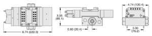
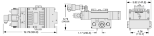
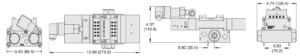
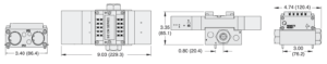
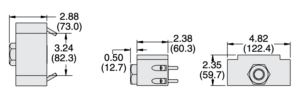
| Dimensions-Inches(mm) | |
Basic Size 0 – Valve and Base assembly | with remote reset and with status indicator switch |
 | |
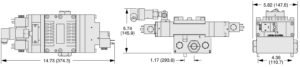
| with solenoid reset and with status indicator switch | |
 | |
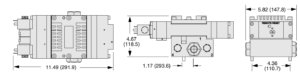
| with remote reset and without status indicator switch | |
 | |
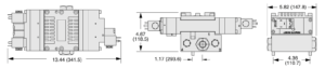
| with solenoid reset and without status indicator switch | |
 | |
Technical Data
Solenoid Pilot Controlled Valves
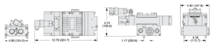
| Dimensions-Inches(mm) | |
| Basic Size 2 – Valve and Base assembly | with remote reset and with status indicator switch |
 | |
| with solenoid reset and with status indicator switch | |
 | |
| with remote reset and without status indicator switch | |
 | |
| with solenoid reset and without status indicator switch | |
 | |
5/2 PRESSURE CONTROLLED VALVES – VALVE AND BASE ASSEMBLY
MODEL NUMBER CONFIGURATOR(4-Way 2-Position Valves)
5/2 Pressure Controlled Valves – Valves, Manifold Bases, and End Stations for Manifold Assemblies
In addition to the manifold, an end station kit with a check valve must be ordered for each assembly. The number of manifolds with a single supply inlet will be limited to the pressure and flow rate of the system. Too many manifolds may result in too large of an internal pressure drop resulting in valve faults. The manifold end station kit with dual inlet check will allow the manifold to be supplied with air from both ends of the assembly.

Valve Operation
| PRESSURE CONTROLLED VALVES | |
| Normal Operation | The valve is operated by pressurizing both pilot supply ports simultaneously. This causes both main valve elements to be actuated so that air from inlet port 1 flows to outlet port 4, but not to port 2. Air downstream of port 2 is exhausted through port 3. When the pilot supply ports are de-pressurized, both valve elements are de-actuated, and air then flows from inlet port 1 to outlet port 2, but no longer to outlet port 4. Air downstream of port 4 is exhausted through port 5. On first operation, or after repair, the pilot valve supply circuit and inherent monitoring elements may need to be reset. |
| Valve Locked-out | Whenever the valve elements operate in a sufficiently asynchronous manner, either on actuation or de-actuation, the valve will move to a locked-out position. In the locked-out position, one crossover and its related timing chamber will be exhausted, and the other crossover and its related timing chamber will be fully pressurized. The valve element (side B) that is partially actuated has pilot air available to fully actuate it, but no air pressure on the return piston to fully de-actuate the valve element. The return springs are limited in travel, and can only return the valve elements to the intermediate (locked-out) position. Sufficient air pressure acting on the return pistons is needed to return the valve elements to a fully home position. |
| Detecting a Malfunction | If the main valve elements are not both actuated or de-actuated synchronously, the valve defaults to the locked-out position so that outlet port 2 receives full inlet pressure, and outlet port 4 is exhausted through port 5. The valve must now be “reset” to resume normal operation. |
| Resetting the Valve | The valve will remain in the locked-out position, even if the inlet air supply is removed and re-applied. A remote reset signal must be applied to reset the valve. Reset is accomplished by momentarily pressurizing the reset port. Actuation of the reset piston physically pushes the main valve elements to their home position. Actuation of the reset piston also opens the reset poppet, thereby, immediately exhausting pilot supply air, thus, preventing valve operation during reset. De-actuation of reset pistons causes the reset poppets to close and pilot supply timing chambers to fully pressurize. Reset pressure can be applied by a remote 3/2 normally closed valve |
| Status Indicator | The optional status indicator pressure switch will actuate when the main valve is operating normally, and will de-actuate when the main valve is in the locked-out position or inlet pressure is removed. This device is not part of the valve lockout function, but, rather, only reports the status of the main valve |
Valve Operation
| Valve Schematic | |
 |
| Pressure Switch Pinout | |
| DIN EN 175301-803 Form A |  |
Technical Data
Pressure Controlled Valves
| Dimensions-Inches(mm) | |
Basic Size 0 – Valve and Base assembly | with remote reset and with status indicator switch |
 | |
| with remote reset and without status indicator switch | |
 | |
| Basic Size 2 – Valve and Base assembly | with remote reset and with status indicator switch |
 | |
| with remote reset and without status indicator switch | |
 | |
Manifold Bases and End Stations
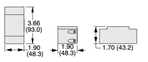
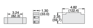
| Dimensions-Inches(mm) | |
| Manifold Base for Basic Size 0 | 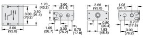 |
| Manifold Base for Basic Size 0 | 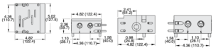 |
| End Station | For Basic Size 0 |
 | |
| For Basic Size 2 | |
 | |
| End Station with Check Valve | For Basic Size 0 |
 | |
| For Basic Size 2 | |
 | |
Accessories
PRESSURE STATUS INDICATION

PREWIRED ELECTRICAL CONNECTORS

 ELECTRICAL CONNECTORS

Related Products
REQUEST QUOTATION

PAYMENT

LINK


