Japan, Ross Asia
Ross Asia DMC2 series double valve Safety Cat 4 PL e, internal monitoring, manual reset
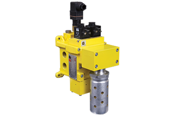
Made in Japan
Manufacturer : Ross Asia
Model : DMC2 series double valve
Safe Exhaust Control Reliable Double Valves DM2® Series C Product Overview
Safe Exhaust Safety Function
The DM2® Series C valve safety function is to shut off supply or pneumatic energy and to exhaust any pneumatic energy from downstream of the valve.

Illustration examples.
The DM2® Series C Safe Exhaust valves are dual valves used to block the supply and remove the downstream pressure from the circuit or machine. It is integrated into the electrical safety system to remove potentially hazardous energy in order to provide employees safe access to a machine or zone. By quickly removing the pneumatic energy with a safety valve, determined by the risk assessment, the safety system integrity is maintained allowing the employee to complete their tasks and safely and rapidly.
VALVE FEATURES
| Redundant Control | Redundant control can achieve Category 4, PL e, when used with proper safety controls |
| Dynamic Monitoring | Monitoring, and air flow control functions are simply integrated into two identical valve elements |
| Dynamic Memory | Asynchronous movement of valve elements is detected by the dynamic monitoring and the valve latches in the safe condition, resulting in a residual outlet pressure of less than 1% of supply |
| Valve Reset | Can only be accomplished by the integrated electrical (solenoid) reset; the valve cannot be reset by removing and re-applying supply pressure |
Poppet Design | Dirt tolerant, wear compensating for quick response and high flow capacity |
PTFE Backup Piston Rings | Enhances valve endurance enabling operation with or without in-line lubrication |
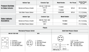
Status Indicator | Includes a pressure switch with both normally open (NO) and normally closed (NC) contacts to provide status feedback to the control system indicating whether the valve is in the lockout or ready-to-run condition |
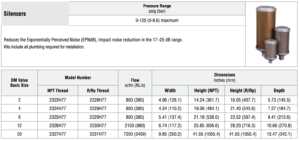
Silencer | High flow, clog resistant silencer included |
Mounting | Base mounted for ease of valve replacement, captive valve-to-base mounting screws |
Flexible Piping | Inlet and outlet ports on both sides (plugs for unused ports included) |
Intermediate Pilots (Basic Size 12 & 30 valves only) | Increases pilot air flow for fast valve response, making it possible to use the same size solenoids as valve |
SISTEMA Library | Available for download |
PRODUCT CREDENTIALS
Specifications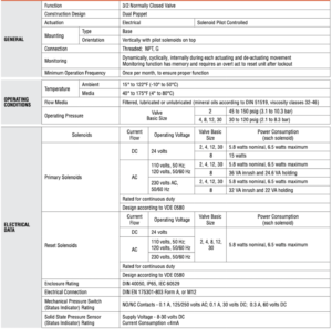

Ordering Information
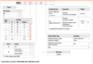
MODEL NUMBER CONFIGURATOR(3-Way 2-Position Valves)

Safety Solutions Options
Safe Air Entry System Assemblies with DM 2® Series C Double Valves
Air Entry System Assemblies with manual Lockout L-O-X ® valve, air preparation FRL combinations, and Safe Exhaust Double Valves are available.
Valve Operation
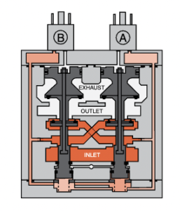
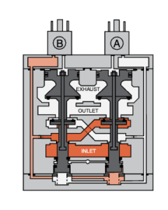
| Valve De-actuated (ready-to-run) | The flow of inlet air pressure into the crossover passages is restricted by the size of the passage between the stem and the valve body opening. Flow is sufficient to quickly pressurize pilot supply/timing chambers A and B. The inlet poppets prevent air flow from crossover passages into the outlet chamber. Air pressure acting on the inlet poppets and return pistons securely hold the valve elements in the closed position. (Air passages shown out of position and reset adapter omitted for clarity. |
 | |
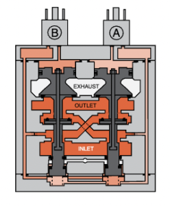
| Valve Actuated | Energizing the pilot valves simultaneously applies pressure to both pistons, forcing the internal parts to move to their actuated (open) position, where inlet air flow to crossover passages is fully open, inlet poppets are fully open and exhaust poppets are fully closed. The outlet is then quickly pressurized, and pressure in the inlet, crossovers, outlet, and timing chambers are quickly equalized. De-energizing the pilots quickly causes the valve elements to return to the ready-to-run position. |
 | |
| Valve Locked-out | Whenever the valve elements operate in a sufficiently asynchronous manner, either on actuation or de-actuation, the valve will move to a locked-out position. In the locked-out position, one crossover and its related timing chamber will be exhausted, and the other crossover and its related timing chamber will be fully pressurized. The valve element (side B) that is partially actuated has pilot air available to fully actuate it, but no air pressure on the return piston to fully de-actuate the valve element. Air pressure in the crossover acts on the differential of side B stem diameters creating a latching force. Side A is in a fully closed position, and has no pilot air available to actuate, but has full pressure on the inlet poppet and return piston to hold the element in the fully closed position. Inlet air flow on side A into its crossover is restricted, and flows through the open inlet poppet on side B, through the outlet into the exhaust port, and from the exhaust port to atmosphere. Residual pressure in the outlet is less than 1% of inlet pressure. The return springs are limited in travel, and can only return the valve elements to the intermediate (locked-out) position. Sufficient air pressure acting on the return pistons is needed to return the valve elements to a fully closed position |
 | |
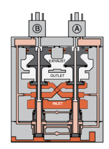
| Resetting the Valve | The valve will remain in the locked-out position, even if the inlet air supply is removed and re-applied. A remote reset signal must be applied to reset the valve. Reset is accomplished by momentarily pressurizing the reset port. Actuation of the reset piston physically pushes the main valve elements to their closed position. Inlet air fully pressurizes the crossovers and holds the inlet poppets on seat. Actuation of the reset piston opens the reset poppet, thereby, immediately exhausting pilot supply air, thus, preventing valve operation during reset (Reset adapter added to illustration.). De-actuation of reset pistons causes the reset poppets to close and pilot supply to fully pressurize. Reset pressure can be applied by a remote 3/2 normally closed valve, or from an optional 3/2 normally closed solenoid mounted on the reset adapter. De-actuation of reset pistons causes the reset poppets to close and pilot supply to fully pressurize. Reset air pressure can be applied by a remote 3/2 normally closed valve, or from an optional 3/2 normally closed solenoid, or a manual push button mounted on the reset adapter |
 | |
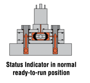
| Status Indicator | The status indicator pressure switch will actuate when the main valve is operating normally, and will de-actuate when the main valve is in the locked-out position or inlet pressure is removed. This device is not part of the valve lockout function, but, rather, only reports the status of the main valve |
 | |
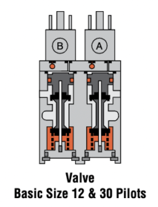 | Basic Size 12 and 30 valves require relatively large pilots to actuate and de-actuate the main valve elements. In order to achieve extremely quick valve response for such large pilots, a 2-stage solenoid pilot system is incorporated into the design. This keeps the required electrical current to operate the pilots to a minimum |
Valve Technical Data
| Valve Schematic | ||
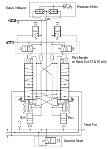 | ||
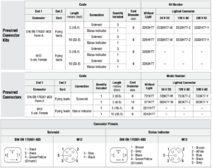
| Solenoid & Pressure Switch Pinouts | ||
| Solenoid | DIN EN 175301-803 Form A | M12 |
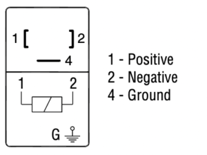 | 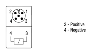 | |
| Pressure Switch | 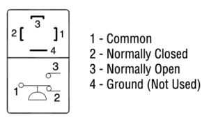 |  |
| Dimensions-Inches(mm) | ||
| Basic Size | Port Size | View X (base mounting hole pattern) |
| 2 | 1/4 & 3/8 | 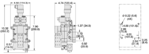 |
| 4 | 1/2 | 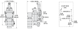 |
| 8 | 3/4 & 1 | 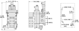 |

| Dimensions-Inches(mm) | ||
| Basic Size | Port Size | View X (base mounting hole pattern) |
| 12 | 1 | 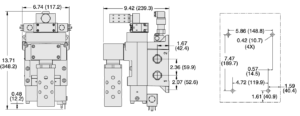 |
| 30 | 2 | 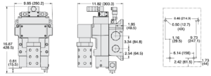 |

Accessories
ELECTRICAL STATUS INDICATION

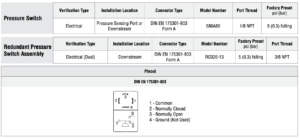
ENERGY RELEASE VERIFICATION

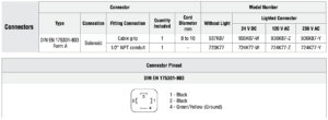
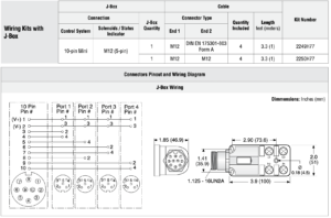
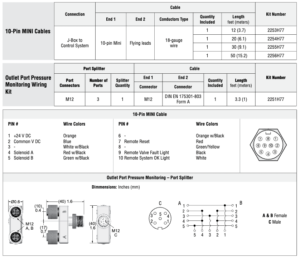
PREWIRED ELECTRICAL CONNECTORS
ELECTRICAL CONNECTORS

JUNCTION BOX OPTIONS

HIGH FLOW NOISE REDUCTION SILENCER KITS
