Japan, Satuma Denki
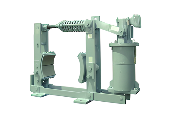
Satuma Denki BFS5-T Lifting Drum Brakes AL – AL Brakes
Made in Japan
Manufacturer : Satuma
Model : BFS5-T
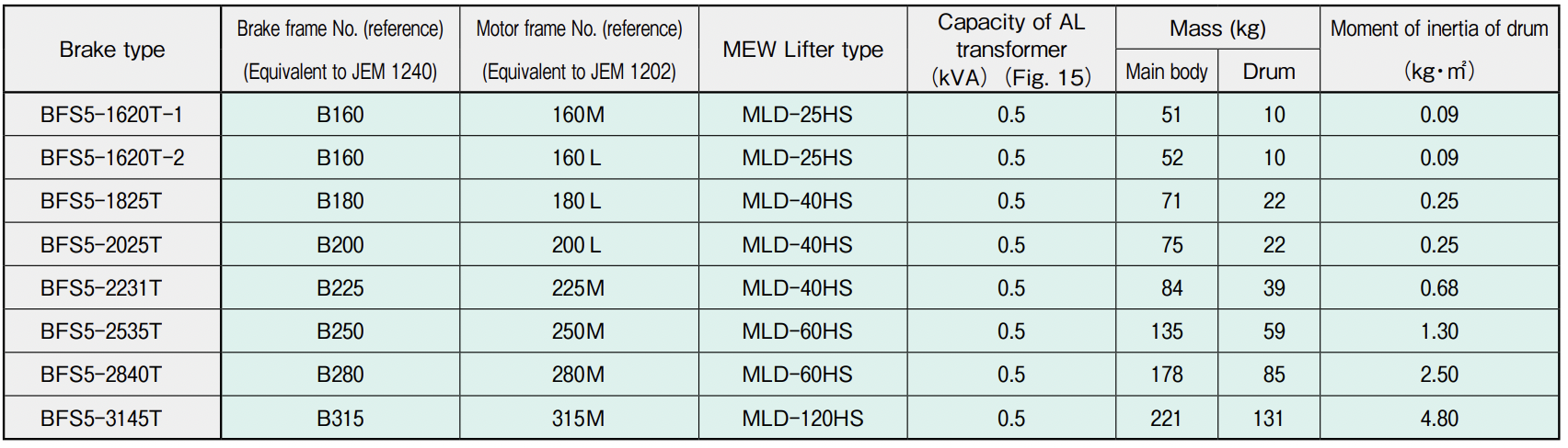
Types and Ratings of Drum Type Brakes
| BFS5-T series Brake AL | Brake Type |
| —— | |
| —— | Applicable standard |
| AL control | Actuation |
| For Speed control | Application |
| – 10°c ~ + 40°c | Ambient temperature |
| Dustproof type (Main unit: Unprotected type) | Protective structure of operation unit |
| Class E insulation | Insulation class of operation unit |
| 200V 50Hz, 220V 60Hz, 400V 50H,z 440V 60Hz | Rated voltage and frequency |
| 15% ED (150s/cycle) | Usage rate of operation unit |
| —— | Actuating cycle |
| Munsell 585/0.5 | Coating color |
Application of Drum Type Brakes to motors
| AL brake | DC electromagnetic brake | Motor | ||||||
| Type of AL brake | Motor output and rated braking torque of brake | Frame Number | Number of poles | |||||
| 40%ED | 60%ED | Consecutive | ||||||
| Motor output (kW) | Rated braking torque(N·m) | Motor output (kW) | Rated braking torque (N·m) | Motor output (kW) | Rated braking torque (N·m) | |||
| -·- -·—– | 2.2 | 98 | 1.8 | 98 | 1.5 | 98 | 132M | 6 |
| 3.7 | 98 | 3 | 98 | 2.8 | 98 | |||
| BFS5-1620T-1 | 5.5 | 98 | 4. 5 | 98 | 4 | 98 | 160M | 6 |
| 7.5 | 127 | 6.3 | 98 | 5.5 | 98 | |||
| BFS5-1620T-2 | 11 | 196 | 9 | 196 | 7.5 | 196 | 160 LEVEL | 6 |
| BFS5- 1825T | 15 | 255 | 13 | 196 | 11 | 196 | 180 L | 6 |
| BS5- 2025T | 22 | 333 | 18.5 | 333 | 15 | 255 | 200L | 6 |
| BFS5- 2231T | 30 | 539 | 25 | 539 | 22 | 539 | 225M | 6 |
| BFS5 – 2535TB | 37 | 706 | 30 | 539 | 25 | 539 | 250M | 6 |
| 45 | 706 | 37 | 706 | 33 | 539 | |||
| BFS5 – 2840TB | 55 | 1270 | 45 | 980 | 37 | 980 | 280M | 8 |
| BFS5 – 3145TB | 75 | 1960 | 63 | 1960 | 50 | 1960 | 315M | 8 |
The AL brake is a special MEW Lifter brake used to control speed (AL control) by connecting a MEW Lifter to the secondary side of a wound-rotor induction motor. When the AL brake is to be used, place a brake for stopping on the coupling side of the motor, and the AL brake on the anti-coupling side.
Specifications and external dimensions of BFS5-T type AL brakes
 Note 1: Shared use for 200 V and 400 V is possible by changing the connection of the MEW Lifter, but shared use for 50- and 60-Hz frequencies is not allowed.
Speed control of crane motors using MEW Lifter (AL-control : Adjustable lowering control)
With a MEW Lifter (electro-hydraulic lifter), the hydraulic pressure of the cylinder room changes by altering the rotation speed of the pilot motor at the top of the lifter, while the lifting force increases or decreases in proportion to the square of the rotation speed of the pilot motor. The AL-control system controls the speed of the wound-rotor motor using this property. Figure A demonstrates the mechanism and connection. By moving the controller from the stop position to the first lowering notch, the wound-rotor motor IM and electromagnetic brake MB are connected to the power supply, the switch SW for MEW Lifter is connected to the R side respectively and the MEW Lifter of the AL brake is excited by the secondary frequency (like the power supply frequency when stopped) via a transformer TR to adjust voltage, generate lifting power and open the brake, whereupon the motor starts rotating. Since the secondary frequency declines with increasing motorrotation speed, the lifting force of the MEW Lifter suddenly falls, as shown by curve A in Fig. B, and becomes 0 at the synchronous rotation speed. Meanwhile, the spring strength for braking the AL brake is shown by linear line B. As shown, there is a state at a certain motor-rotation speed where the lifting force of the MEW Lifter is in equilibrium with the spring strength, allowing the brake shoe to rotate while slightly in contact with the brake drum. If the motor-rotation speed increases slightly further from this state, the lifting force declines below the spring strength, allowing an increase in braking force and reducing the motorrotation speed. If the motor-rotation speed declines slightly, the braking power decreases to increase the rotation speed, and the motor continues stable operation accordingly. Specifically, assuming the synthetic torque of curves A and B to be C, the sum of the generated torque D of the motor and curve C when a resistor is inserted is shown by curve E (fedba.) When the load is 0, winding operation is performed at the speed of point d. At stable speed under a rated load, the lowering characteristics are improved as shown by point b, allowing stable low-speed lowering torque characteristics to be obtained
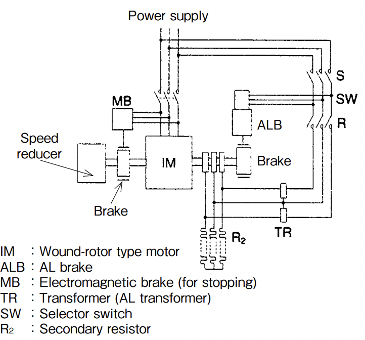
Fig. A Mechanism and connection
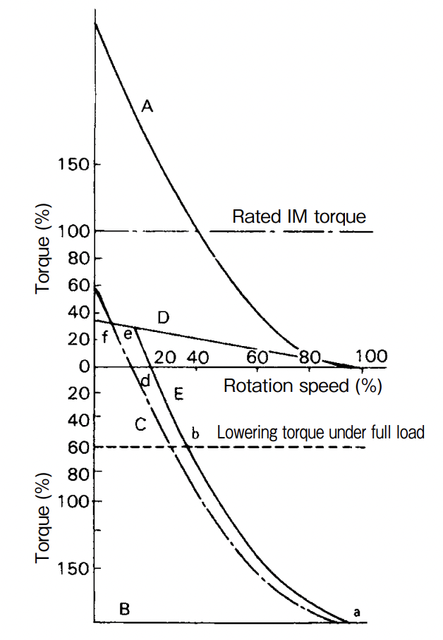
Fig. B Operation characteristics of AL brake
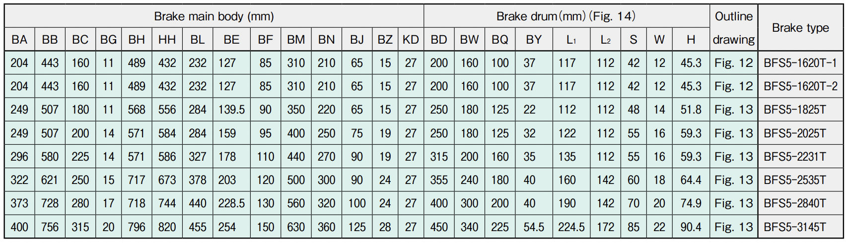
Note 2: Use the brake drum for the AL brake as specified by Satuma (Fig. 14.) The brake drums for BFS5-1620T to 2231T are made of gray cast iron (FC250), and those for BFS5-2535T to 3145T are made of spherical graphite cast iron (FCD400.)
Related Products
REQUEST QUOTATION

PAYMENT

LINK


