Japan, Satuma Denki
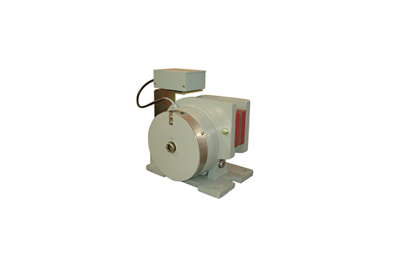
Satuma Denki PB3-PL3-Series Pad-type Disk Brakes AC-operated DC Electromagnetic System
Made in Japan
Manufacturer : Satuma
Model : PB3-PL3-Series
The AC-operated DC electromagnetic pad-type disk brakes is an off brake that delivers stable braking performance with excellent features, including easy maintenance and low noise. This high-performance brake was newly developed for applications such as braking for traversing and traveling of cranes, braking of carriages and roller conveyers, etc., and for maintenance purposes. It is becoming more popular than conventional drum-type brakes.
Features
• Simple structure, compact, and lightweight Since the mechanism generating braking force integrates magnets and a braking spring on the side face of the disk rotor, this ensures a simple, compact, and lightweight structure. The brake is thus extremely easy to install, maintain and handle.
• Stable braking force Compared to drum-type brakes, the disk brake has a large heat-dissipation area, ensuring a large braking workload. This allows stable braking performance from low to high rotation speeds.
• Small shock and low braking noise Since the stroke of the movable part of the magnet is small, shock generated when braking and opening is minimized, and the braking noise is also low.
• Shortened maintenance time Adopting a dry bushing decreases lubrication work.
Rating
| Brake Type | Type PB3: Brake for traversing and traveling of cranes, carriages, and for roller conveyers (not usable for hoisting.) Type PL3: Brake for retaining: To prevent swinging of cranes (not usable for hoisting) |
| Installation method | Standard specification/floor installation typeNote 1, Special specifications/wall-mount type (axis: perpendicular) Types V and Z, wall-mount type (axis: horizontal): type K |
| Actuation | Off brake |
| Ambient temperature | – 10 ~ +40°C |
| Protective structure of operation unit | Simple dustproof type (Main body: Unprotected type) |
| Insulation class of operation unit | Class F insulation |
| Rated voltage and frequency | 200/220 V − 50/60Hz or 400/440V − 50/60Hz Note 2 |
| Permissible voltage fluctuation | – 15 ~ + 10% |
| Usage rate of operation unit and actuating cycle (for braking) | 100%, 400 cycle/hour |
| Time rating (for maintenance) | Continuous |
| Coating color | Munsell 7.5BG6/1.5 |
Note. 1: Mountable to both sides, provided that the inclination from the horizontal shaft is up to ±45°.
Note. 2: 200- and 400 V-class brakes can be used by changing the terminal connections.
Specifications
| Brake Type | PB3 – 3 | PB3 – 6 | PB3 – 12 |
| Rated braking torque (N・m) | 15~30 | 30~60 | 60~120 |
| Permissible braking workload (J/min) | 20,000 | 32,000 | 49,000 |
| Permissible maximum braking workload (J) | 129,000 | 192,000 | 287,000 |
| Permissible braking rotational speed (min-1) | 2300 | 1800 | 1600 |
| Suction time of brake (s) Note 3) | 0.15 | 0.25 | 0.30 |
| Detachment time of brake (s) Note 3 | 0.30 | 0.35 | 0.45 |
| Standard disk rotor dimensions, Outer diameter×thickness (mm) Note4, Note5 | 250X 12 | 300 X 12 | 350X 12 |
| Moment of inertia of the disk rotor (kg・m2 ) | 0.038 | 0.075 | 0.14 |
| Mass: Main body/disk rotor (kg) | 14/7 | 24/12 | 40 / 18 |
Note. 3: The operating time is the value at the rated braking torque and specified stroke
Note 4: The disk rotor is made of gray cast iron (FC250.)
Note 5: Applicable by special processing, provided that the disk-rotor thickness ranges from 10 to 15 mm (PB3-12: 10 to 20 mm.)
| Brake type | PL3- 5 | PL3- 10 | PL3- 20 |
| Rated torque (N · m) | 50 | 100 | 200 |
| Standard disk rotor dimensions, Outer diameter×thickness (mm)Note6, Note7 | 250X 12 | 300 X 12 | 350X 12 |
| Mass: Main body/disk rotor (kg) | 14/7 | 24/12 | 40/ 18 |
Note.6 : The disk rotor is made of gray cast iron (FC250.)
Note.7: Applicable by special processing, provided that the disk-rotor thickness ranges from 10 to 15 mm (PL3-20: 10 to 20 mm.)
External dimensions and structure
External dimensions (mm)
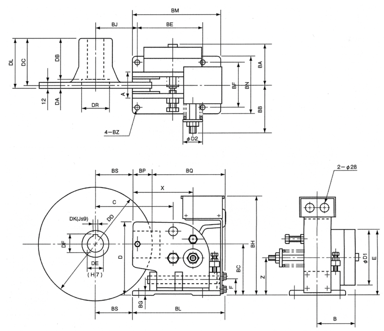
| Brake type | Brake main body (mm) | |||||||||||||||
| For braking | For retaining | BE | BF | BJ | BM | BN | BC | BA | BB | BG | BH | BL | BP | BQ | BS | BZ |
| PB3- 3 | PL3- 5 | 135 | 100 | 95 | 185 | 130 | 112 | 95 | 105 | 10 | 230 | 195 | 40 | 155 | 85 | 10 |
| PB3-6 | PL3-10 | 165 | 120 | 115 | 225 | 150 | 132 | 110 | 130 | 12 | 260 | 235 | 50 | 185 | 100 | 12 |
| PB3-12 | PL3-20 | 195 | 140 | 130 | 270 | 180 | 160 | 130 | 145 | 15 | 300 | 285 | 65 | 220 | 110 | 15 |
Note.8: For axis diameters and key dimensions (tolerance) other than those listed above, items with unprocessed axial diameter (DE) are available. Please process them to the desired dimensions yourself.
Structural drawing of disk brake
This disk brake has a simple structure, with only one pin unit as the supporting point.
• Major parts include a brake base, arm A which integrates a DC electromagnet, and arm B.
• The electromagnetic coil is fastened by MEW Resin (epoxy resin), increasing the insulation performance.
• Since a bolt for opening the manual brake is provided, the brake can be opened easily.
• There are three adjustment parts: adjustment of the gap on both sides of the lining, magnet stroke adjustment, and braking torque (brake spring) adjustment. In particular, the braking torque is easily adjustable because the braking spring is installed outside.
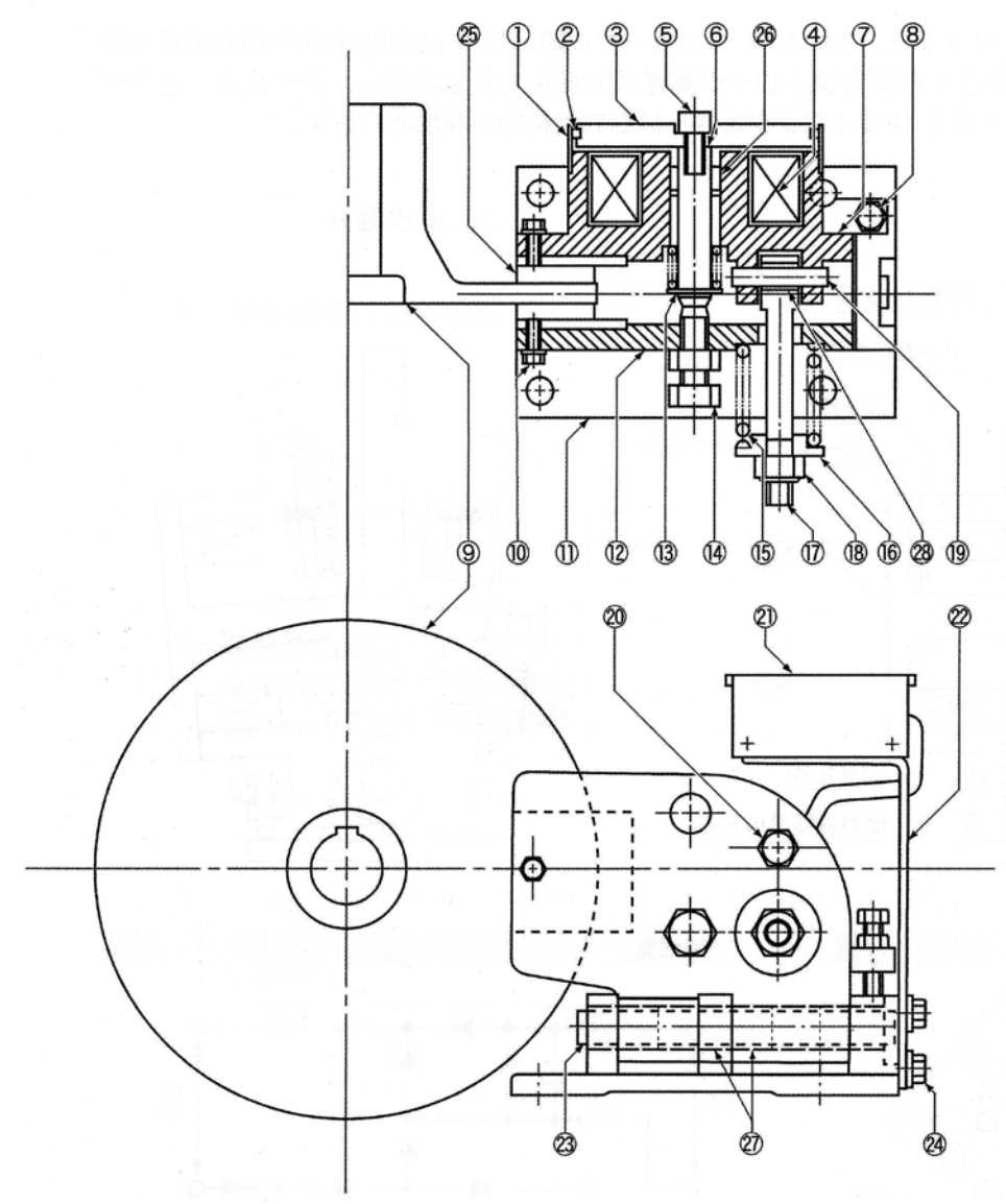
| 1 | Cover | 15 | Braking spring |
| 2 | Packing | 16 | Spring holder |
| 3 | Suction disk | 17 | Braking spring adjustment bolt |
| 4 | Coil | 18 | Braking spring adjustment nut |
| 5 | Suction disk mounting bolt | 19 | Connecting pin (with bushing) |
| 6 | Rod | 20 | Manual release bolt |
| 7 | Arm A | 21 | Control box |
| 8 | Tilt adjustment bolt | 22 | Bracket |
| 9 | Disk rotor (option) | 23 | Connecting pin (with bushing) |
| 10 | Lining mounting bolt | 24 | Bracket mounting bolt |
| 11 | Brake base | 25 | Lining (pad) |
| 12 | Arm B | 26 | Dry bushing |
| 13 | Suction disk returning spring | 27 | Dry brushing |
| 14 | Stroke adjustment bolt | 28 | Dry bushing |
| Disk rotor (option) | ||||||||||||||||||||
| A | B | C | D | E | F | ∅ D1 | X | Z | ∅ D2 | Mass | DD | DA | DB | DC | DL | DR | DE | DF | DN | Mass |
| 58 | 90 | 170 | 162 | 150 | 32 | 135 | 125 | 82 | 35 | 14kg | 250 | 20 | 82 | 96 | 102 | 50 | 32 | 35.3 | 10 | 7kg |
| 68 | 104 | 205 | 192 | 175 | 42 | 155 | 155 | 97 | 49 | 24kg | 300 | 8 | 112 | 114 | 120 | 70 | 42 | 45.3 | 12 | 12kg |
| 86 | 121 | 235 | 230 | 210 | 50 | 190 | 185 | 115 | 63 | 40kg | 350 | 23 | 112 | 129 | 135 | 85 | 48 | 51.8 | 14 | 18kg |
| 55 | 59.3 | 16 | ||||||||||||||||||
Description of operation
• Braking operation When the current of the DC electromagnetic coil ④ is set to OFF, arms A ⑦ and B ⑫ move toward each other by the braking spring ⑮ with the connecting pin ㉓ used as a supporting point. Consequently the lining ㉕ fastened to arms A ⑦ and B ⑫ presses down the disk rotor ⑨ , thus generating braking force.
• Releasing operation When the current of the DC electromagnetic coil ④ is set to ON, the yoke and suction disk ③ of arm A ⑦ exceed the force of the braking spring ⑮ , and are attracted to each other. At this time, the rod ⑥ presses the tip of the stroke-adjustment bolt ⑭ , arms A ⑦ and B ⑫ detach, and the disk rotor ⑨ detaches from the lining ㉕ , discharging the braking force.

General expressions used for brake calculations

When ordering and making an inquiry Please inform us of the following:
1.Application: Crane type, classification (traversing, traveling), usage rate, Rating of operations (cycle/hour), moment of inertia of the load
2.Operation environment: Indoor/outdoor use, ambient temperature
3.Brake type and Diskrotor diameter
4.Motor rating: Output/load hour rate, voltage, frequency (availability of inverter control regenerative braking)
5.Braking torque
6.Operation power supply: voltage, frequency
7.Special accessory (as applicable) : disk rotor, etc.
8.Spare parts
Related Products
-
Chiyoda Tsusho CSB-M5F/01F/02F/03F/04F SHOULDER HEAD Flat Type (CSB-F Type)
-
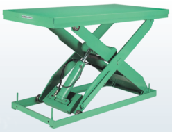
SUGIYASU NX Series Lift Table
-
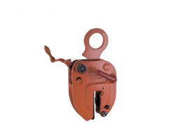
Eagle Clamp NE Type Clamp For Steel
-
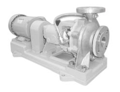
Honda Kiko HAS Stainless Pumps
-
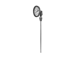
NAGANO KEIKI TB4_ Bimetal Thermometer made with metals
-
Kamoi Kakoshi No.220 Adhesive Tape for Light Washi Paper Wrapping (7 Colors)
REQUEST QUOTATION

PAYMENT

LINK


