Suntest
Suntest IGY4 Series
Manufacturer: Suntest Co.,Ltd
Model: IGY4 Series
Magnetostrictive Displaiacement Transducer
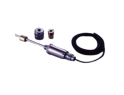
 Model GY Series are “Displacement Transducers” employing magnetostrictive phenomena, especially the Wiedemann effect. An ultra-sonic wave is generated by a moving magnet operating near a magnetostrictive wave guide on which the sonic wave propagates up to the head of the transducer.
The propagation time is precisely measured by state of the art technology and then the absolute displacement transducer is operational.
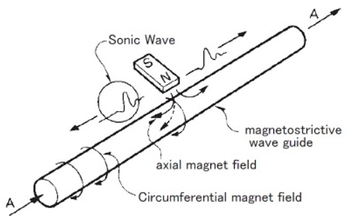
[ Principle ]
The figure shows the fundamental principle of operation.
When a current pulse like A is given to the wave guide, it generates a circumferential magnetic field on the wave guide, then placement of the movable magnet (polarized axially) as shown, only the axial magnetic field of the magnet affecting the wave guide produces a resultant field as indicated by the dotted line.
The vector combination of these two fields produces torsional strain, a phenomenon known as the Wiedemann Effect.
It is a form of vibration and propagates along the wave guide in the form of a transverse ultra-sonic wave.
The GY series displacement transducers detect the propagation time of the ultra-sonic wave.
IGY4 Series
Intrinsic safety structure
◆Explosion-proof symbol : Ex iaⅡ CT4, AT4
◆Possible to use it in Class 0 hazardous area.
◆Class A grounding (first class grounding) isn’t necessary.
It’s the displacement sensor of intrinsic safety type which can be used at zone 0 (Class 0 hazardous area) and is also possible to use for high accuracy level sensor. This is the new product of fourth generation. The Class A grounding (first-class grounding) is unnecessary like the 4th generation. You can select “ExiaⅡAT4” which can be used for long stroke (max.3m) in addition to the explosion protection symbol “ExiaⅡCT4”.
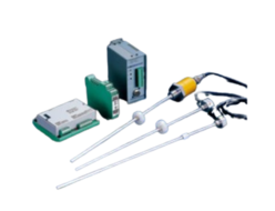
<Controller>
- Analogue output type: GYHC
- Digital output type: GYDC-05 、GYDC-S1
- IRDS-GY When using the IRDM, you can connect with CC-Link, CC-Link IE Field, PROFIBUS, EtherNet/IP, and EtherCAT.
Specifications
| Non-linearity | ≦±0.025%FS Typ. |
|---|---|
| Resolution | (Analogue) 16bit (1/65536) (Digital) Min. 0.1mm |
| Repeatability | ≦±0.01%FS |
| Temp. drift | probe :≦±20ppmFS /°C separator :≦±20ppmFS /°C |
| Power supply | separator :AC90〜110V 50/60Hz |
| Max. Pressure | probe rod :35MPa |
| Operating temp. | probe :-20°C〜+60°C separator :-20°C〜+50°C |
| Storage temp. | -40°C〜+80°C(probe) |
| Vibration | 6G(40Hz 2mmPP)(probe) |
| Shock | 100G(2msec)(probe) |
| Waterproof | probe head :waterproof structure(*) |
| Cable | Std. 1.5m (possible to extend 200m using the dedicated cable) |
- The above mentioned accuracy applies to sensors with an effective stroke of 300mm or more.
(*)It can be endured by using for 30 minutes in max. 1m of water depth. (It can’t be used for the application of submerged continuously.)
Model No.
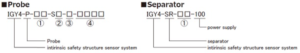
① Target dense fog and steamy classification
2C : Suitable for all gases group including hydrogen
2A : Suitable for gases group such as gasoline
② Thread
M : M24xP1.0 (Std.)
N : M18xP1.5
U : 3/4-16UNF-3A
G : G3/4
R : R3/4
③ Rod diameter
1 : Φ10 (Std.)
3 : Φ13.8
8 : Φ8
④ Effective stroke
in case of 2C : 50〜2000mm
in case of 2A : 50〜3000mm
(Max. length depends on a using magnet or float.)
* Associated magnet or float
| magnet | float |
|---|---|
| T144, T163, BA, AS, MG30 | F28S, F30S, F40S F42S, F50F, F54S |
- Please consult our factory in case of requesting special magnet or float.
- This model code means only specifying associated magnet or float.
- Ordering magnet or float individually.
| Rating of safety part | explosion protection symbol | Exia II CT4 | Exia II AT4 |
|---|---|---|---|
| Form official approval pass symbol | No. TC19303 (in July 2010) | No. TC20073 (in November 2011) | |
| intrinsic safety circuit | max. voltage 17.22V max. current 89.3mA max. power 0.385W | max. voltage 25.2V max. current 116.5mA max. power 0.734W | |
| non intrinsic safety circuit | power supply AC100V 50/60HzOutput circuit allowable voltage AC110V 50/60Hz DC110V | power supply AC100V 50/60HzOutput circuit allowable voltage AC110V 50/60Hz DC110V |
[ Features ]
① Ex・・・Intrinsic safety structure based upon international standards
② Class A grounding (first class grounding) isn’t necessary adopting a power transformer
and photo coupler isolation system.
③ The probe can be used at Class 0 hazardous zone.
④ Possible to use max. stroke 2000mm(*1)
⑤ The cable between probe and separator can be extended max. 200m by using the dedicated cable.
(*1)Possible to use max. stroke 3000mm using ExiaⅡAT4
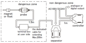
[ Construction ]
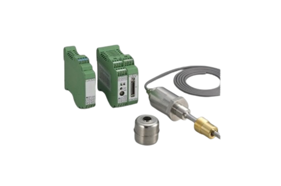
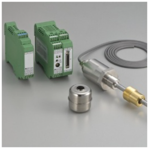
● IGY4 series consist of a probe, a separator, a controller, a magnet (or a float), cable between
probe and separator, and 1m cable between separator and controller.
(*Plastic magnet or float can’t be used by law.)
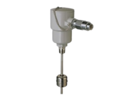
● Probe has 1.5m cable with it.In case of extending cable, it is possible to extend max.
200m by using the dedicated cable (2 core with shield).
Please connect extend cable with 1.5m cable of probe in terminal box.
● Probe and magnet (or float) should be installed in dangerous zone, and separator and controller
should be installed in non dangerous zone.
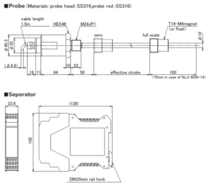
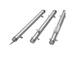
Dimensions
Dimension of Probe & Separator
REQUEST QUOTATION

PAYMENT

LINK


