Drilling And Cutting, Hand Tools, Japan, Miyakawa
Miyakawa S Type Multi-axis Drill
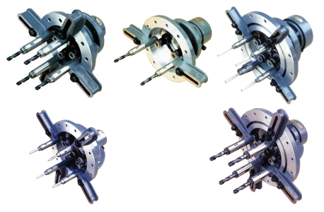
Product Made in Japan
Manufacturer: Miyakawa
Model: S-96, S-130, S-160, , S-204, S-200
S-96 (For 2-axis pitch 10 mm to 100 mm)
Overview
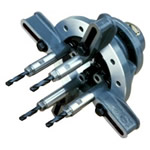 | A: Outer diameter of main shaft quill diameter B: Outer diameter of main shaft C: Length of main shaft end D: Outer diameter of flange of main shaft quill E: Thickness of flange of main shaft quill F: JT or MT number | J Jacobs taper | M Morse taper | M Morse taper |
Performance specification
| Model used Drilling machine | Screw used | Model | Types of chucks | Maximum axial distance (mm) | Minimum axis range of 4 axes (mm) | Minimum axis distance between two axes (mm) | Drilling ability per axis S45C (mm) | Screw standing capacity per axis S45C (M) | Maximum clamp diameter of chuck (mm) | Weight with 4 axes (kg) |
 |  | S – J 96 | C-4 | 83 | 41 | 10 | 3 | 3 | 4 | 4.8 |
| C-6-14 * | 92 | 32 | 14 | 3 | 4 | 6 | 5.1 | |||
| C-6 | 96 | 28 | 15 | 4 | 4 | 6 | 5.2 | |||
| C-10 | 100 | 32 | 22 | 6 | 5 | 10 | 5.7 | |||
| JT-D 5 | 100 | 39 | 27.5 | 4 | 3 | 5 | 5.6 | |||
| JT-1 | 100 | 54 | 37.5 | 5 | 5 | 6.5 | 5.6 | |||
| JT-2 | 100 | 65 | 45.5 | 6 | 5 | 10 | 5.7 | |||
 |  | S – 2M96 | C-4 | 83 | 41 | 10 | 3 | 3 | 4 | 6.5 |
| C-6-14 * | 92 | 32 | 14 | 3 | 4 | 6 | 6.8 | |||
| C-6 | 96 | 28 | 15 | 4 | 4 | 6 | 6.9 | |||
| C-10 | 100 | 32 | 22 | 6 | 5 | 10 | 7.4 | |||
| JT-D 5 | 100 | 39 | 27.5 | 4 | 3 | 5 | 7.3 | |||
| JT-1 | 100 | 54 | 37.5 | 5 | 5 | 6.5 | 7.3 | |||
| JT-2 | 100 | 65 | 45.5 | 6 | 5 | 10 | 7.4 | |||
 |  | S- 3 M 96 | C-4 | 83 | 41 | 1 | 3 | 3 | 4 | 7.0 |
| C-6-14 * | 92 | 32 | 14 | 3 | 4 | 6 | 7.2 | |||
| C-6 | 96 | 28 | 15 | 4 | 4 | 6 | 7.3 | |||
| C-10 | 100 | 32 | 22 | 6 | 5 | 10 | 7.8 | |||
| JT-D 5 | 100 | 39 | 27.5 | 4 | 3 | 5 | 7.8 | |||
| JT-1 | 100 | 54 | 37.5 | 5 | 5 | 6.5 | 7.8 | |||
| JT-2 | 100 | 65 | 45.5 | 6 | 5 | 10 | 7.9 | |||
※ C-6-14 uses a thin spindle. | ||||||||||
Use model icon
Geometry
| Type S – J 96 | Model S-2M96 | Model S-3M96 |
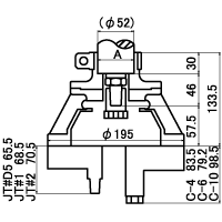 | 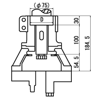 | 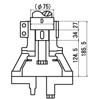 |
| The dimensions in the above figure are part of an attachable drilling machine and screw spindle. Detailed dimensions regarding actual model to be installed may be different, so please contact our service center. | ||
S-130 (for 2-axis pitch 19 mm to 130 mm)
Overview
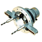 | A: Outer diameter of main shaft quill diameter B: Outer diameter of main shaft C: Length of main shaft end D: Outer diameter of flange of main shaft quill E: Thickness of flange of main shaft quill F: JT or MT number | J Jacobs taper | M Morse taper | M Morse taper |
Performance specification
| Model used Drilling machine | Screw used | Model | Types of chucks | Maximum axial distance (mm) | Minimum axis range of 4 axes (mm) | Minimum axis distance between two axes (mm) | Drilling ability per axis S45C (mm) | Screw standing capacity per axis S45C (M) | Maximum clamp diameter of chuck (mm) | Weight with 4 axes (kg) |
 |  | S – J 130 | C-6 | 130 | 30 | 19 | 5 | 5 | 6 | 6.7 |
| C-10 | 130 | 32 | 22 | 7 | 6 | 10 | 7.6 | |||
| JT-D 5 | 130 | 39 | 27.5 | 4 | 3 | 5 | 7.5 | |||
| JT-1 | 130 | 54 | 37.5 | 6 | 5 | 6.5 | 7.0 | |||
| JT-2 | 130 | 65 | 45.5 | 7 | 6 | 10 | 7.6 | |||
| MT-1 | 130 | 37 | 26 | 7 | 6 | 14 | 8.0 | |||
 |  | S – 2 M 130 | C-6 | 130 | 30 | 19 | 5 | 5 | 6 | 7.6 |
| C-10 | 130 | 32 | 22 | 7 | 6 | 10 | 7.7 | |||
| JT-D 5 | 130 | 39 | 27.5 | 4 | 3 | 5 | 7.6 | |||
| JT-1 | 130 | 54 | 37.5 | 6 | 5 | 6.5 | 7.6 | |||
| JT-2 | 130 | 65 | 45.5 | 7 | 6 | 10 | 7.7 | |||
| MT-1 | 130 | 37 | 26 | 7 | 6 | 14 | 8.1 | |||
 |  | S – 3 M 130 | C-6 | 130 | 30 | 19 | 5 | 5 | 6 | 7.4 |
| C-10 | 130 | 32 | 22 | 7 | 6 | 10 | 8.1 | |||
| JT-D 5 | 130 | 39 | 27.5 | 4 | 3 | 5 | 7.9 | |||
| JT-1 | 130 | 54 | 37.5 | 6 | 5 | 6.5 | 8.0 | |||
| JT-2 | 130 | 65 | 45.5 | 7 | 6 | 10 | 8.1 | |||
| MT-1 | 130 | 37 | 26 | 7 | 6 | 14 | 8.3 | |||
 |  | S – 4M130 | C-6 | 130 | 30 | 19 | 5 | 5 | 6 | 7.5 |
| C-10 | 130 | 32 | 22 | 7 | 6 | 10 | 8.2 | |||
| MT-1 | 130 | 37 | 26 | 7 | 6 | 14 | 8.4 | |||
Use model icon (Click to go to the list)
Geometry
| Model S-J130 | Model S-2M130 | Model S-3M130 |
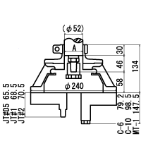 | 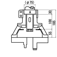 | 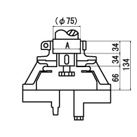 |
| The dimensions in the above figure are part of an attachable drilling machine and screw spindle. Detailed dimensions regarding actual model to be installed may be different, so please contact our service center. | ||
S-160 (for 2-axis pitch 19 mm to 160 mm)
Overview
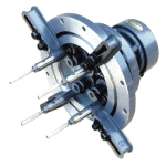 | A: Outer diameter of main shaft quill diameter B: Outer diameter of main shaft C: Length of main shaft end D: Outer diameter of flange of main shaft quill E: Thickness of flange of main shaft quill F: JT or MT number | J Jacobs taper | M Morse taper | M Morse taper |
Performance specification
| Model used Drilling machine | Screw used | Model | Types of chucks | Maximum axial distance (mm) | Minimum axis range of 4 axes (mm) | Minimum axis distance between two axes (mm) | Drilling ability per axis S45C (mm) | Screw standing capacity per axis S45C (M) | Maximum clamp diameter of chuck (mm) | Weight with 4 axes (kg) |
 |  | S – J 160 | C-6 | 150 (160) | 50 | 19 (25) | 5 | 5 | 6 | 12.3 |
| C-10 | 160 | 40 | 25 | 8 | 6 | 10 | 13.1 | |||
| C-13 | 160 | 47 | 33 | 10 | 8 | 13 | 20.7 | |||
| JT-D 5 | 160 | 47 | 33 | 4 | 3 | 5 | 14.3 | |||
| JT-1 | 160 | 54 | 37.5 | 6 | 5 | 6.5 | 14.4 | |||
| JT-2 | 160 | 65 | 45.5 | 8 | 6 | 10 | 14.4 | |||
| JT No. 6 | 160 | 76 | 53.5 | 10 | 8 | 13 | 18.9 | |||
| MT-1 | 160 | 47 | 33 | 12 | 8 | 14 | 21.9 | |||
 |  | S – 2M160 | C-6 | 150 (160) | 50 | 19 (25) | 5 | 5 | 6 | 13.8 |
| C-10 | 160 | 40 | 25 | 8 | 6 | 10 | 14.6 | |||
| C-13 | 160 | 47 | 33 | 10 | 8 | 13 | 17.8 | |||
| JT-D 5 | 160 | 47 | 33 | 4 | 3 | 5 | 15.8 | |||
| JT-1 | 160 | 54 | 37.5 | 6 | 5 | 6.5 | 15.8 | |||
| JT-2 | 160 | 65 | 45.5 | 8 | 6 | 10 | 15.9 | |||
| JT No. 6 | 160 | 76 | 53.5 | 10 | 8 | 13 | 16.0 | |||
| MT-1 | 160 | 47 | 33 | 12 | 8 | 14 | 18.6 | |||
 |  | S – 3 M 160 | C-6 | 150 (160) | 50 | 19 (25) | 5 | 5 | 6 | 13.8 |
| C-10 | 160 | 40 | 25 | 8 | 6 | 10 | 14.6 | |||
| C-13 | 160 | 47 | 33 | 10 | 8 | 13 | 17.8 | |||
| JT-D 5 | 160 | 47 | 33 | 4 | 3 | 5 | 15.7 | |||
| JT-1 | 160 | 54 | 37.5 | 6 | 5 | 6.5 | 15.8 | |||
| JT-2 | 160 | 65 | 45.5 | 8 | 6 | 10 | 15.9 | |||
| JT No. 6 | 160 | 76 | 53.5 | 10 | 8 | 13 | 16.0 | |||
| MT-1 | 160 | 47 | 33 | 12 | 8 | 14 | 18.6 | |||
 |  | S – 4M160 | C-6 | 150 (160) | 50 | 19 (25) | 5 | 5 | 6 | 16.7 |
| C-10 | 160 | 40 | 25 | 8 | 6 | 10 | 17.5 | |||
| C-13 | 160 | 47 | 33 | 10 | 8 | 13 | 20.7 | |||
| JT-D 5 | 160 | 47 | 33 | 4 | 3 | 5 | 18.7 | |||
| JT-1 | 160 | 54 | 37.5 | 6 | 5 | 6.5 | 18.8 | |||
| JT-2 | 160 | 65 | 45.5 | 8 | 6 | 10 | 18.9 | |||
| JT No. 6 | 160 | 76 | 53.5 | 10 | 8 | 13 | 18.9 | |||
| MT-1 | 160 | 47 | 33 | 12 | 8 | 14 | 21.5 | |||
Use model icon (Click to go to the list)
Geometry
| S-J160 type | Model S-2M160 | Model S-3M160 | Model S-4M160 |
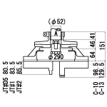 | 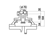 | 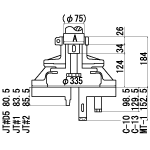 | 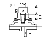 |
| The dimensions in the above figure are part of an attachable drilling machine and screw spindle. Detailed dimensions regarding actual model to be installed may be different, so please contact our service center. | |||
S-200 (for 2-axis pitch 29.5 mm to 200 mm)
Overview
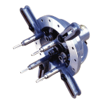 | A: Outer diameter of main shaft quill diameter B: Outer diameter of main shaft C: Length of main shaft end D: Outer diameter of flange of main shaft quill E: Thickness of flange of main shaft quill F: JT or MT number | J Jacobs taper | M Morse taper | M Morse taper |
Performance specification
| Model used Drilling machine | Screw used | Model | Types of chucks | Maximum axial distance (mm) | Minimum axis range of 4 axes (mm) | Minimum axis distance between two axes (mm) | Drilling ability per axis S45C (mm) | Screw standing capacity per axis S45C (M) | Maximum clamp diameter of chuck (mm) | Weight with 4 axes (kg) |
 |  | S – J 200 | C-13 * | 200 | 42 | 29.5 | 10 | 8 | 13 | 19.4 |
| JT-D 5 | 200 | 42 | 29.5 | 4 | 3 | 5 | 18.0 | |||
| JT-1 | 200 | 54 | 37.5 | 6 | 5 | 6.5 | 18.0 | |||
| JT-2 | 200 | 65 | 45.5 | 8 | 6 | 10 | 18.4 | |||
| JT No. 6 | 200 | 76 | 53.5 | 10 | 8 | 13 | 18.5 | |||
| MT-1 | 200 | 42 | 29.5 | 10 | 10 | 14 | 19.5 | |||
 |  | S – 2 M 200 | C-13 * | 200 | 42 | 29.5 | 10 | 8 | 13 | 20.4 |
| JT-D 5 | 200 | 42 | 29.5 | 4 | 3 | 5 | 19.7 | |||
| JT-1 | 200 | 54 | 37.5 | 6 | 5 | 6.5 | 19.8 | |||
| JT-2 | 200 | 65 | 45.5 | 8 | 6 | 10 | 19.9 | |||
| JT No. 6 | 200 | 76 | 53.5 | 10 | 8 | 13 | 20.0 | |||
| MT-1 | 200 | 42 | 29.5 | 10 | 10 | 14 | 21.0 | |||
 |  | S – 3 M 200 | C-13 * | 200 | 42 | 29.5 | 10 | 8 | 13 | 20.7 |
| JT-D 5 | 200 | 42 | 29.5 | 4 | 3 | 5 | 20.0 | |||
| JT-1 | 200 | 54 | 37.5 | 6 | 5 | 6.5 | 20.1 | |||
| JT-2 | 200 | 65 | 45.5 | 8 | 6 | 10 | 20.2 | |||
| JT No. 6 | 200 | 76 | 53.5 | 10 | 8 | 13 | 20.3 | |||
| MT-1 | 200 | 42 | 29.5 | 10 | 10 | 14 | 21.5 | |||
| ※ The minimum axis range of same speed tapping is 31 mm | ||||||||||
Use model icon (Click to go to the list)
Geometry
| S – J 200 type | S-2M 200 type | S-3M 200 type |
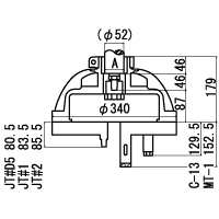 | 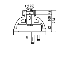 | 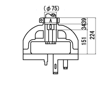 |
| The dimensions in the above figure are part of an attachable drilling machine and screw spindle. Detailed dimensions regarding actual model to be installed may be different, so please contact our service center. | ||
S-204 (for 2-axis pitch 29.5 mm to 204 mm)
Overview
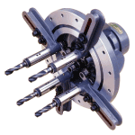 | A: Outer diameter of main shaft quill diameter B: Outer diameter of main shaft C: Length of main shaft end D: Outer diameter of flange of main shaft quill E: Thickness of flange of main shaft quill F: JT or MT number | J Jacobs taper | M Morse taper | M Morse taper |
Performance specification
| Model used Drilling machine | Screw used | Model | Types of chucks | Maximum axial distance (mm) | Minimum axis range of 4 axes (mm) | Minimum axis distance between two axes (mm) | Drilling ability per axis S45C (mm) | Screw standing capacity per axis S45C (M) | Maximum clamp diameter of chuck (mm) | Weight with 4 axes (kg) |
 |  | S- 3 M 204 | C-13 * | 200 | 42 | 29.5 | 10 | 10 | 13 | 27.0 |
| JT-D 5 | 200 | 42 | 29.5 | 4 | 3 | 5 | 20.0 | |||
| JT-1 | 200 | 54 | 37.5 | 6 | 5 | 6.5 | 20.1 | |||
| JT-2 | 200 | 65 | 45.5 | 8 | 6 | 10 | 26.8 | |||
| JT No. 6 | 200 | 76 | 53.5 | 10 | 8 | 13 | 27.8 | |||
| MT-1 | 200 | 42 | 29.5 | 13 | 12 | 14 | 33.1 | |||
| MT-2 | 200 | 54 | 37.5 | 19 | 14 | 23 | 34.1 | |||
 |  | S – 4M204 | C-13 * | 200 | 42 | 29.5 | 10 | 10 | 13 | 26.8 |
| JT-D 5 | 200 | 42 | 29.5 | 4 | 3 | 5 | 25.9 | |||
| JT-1 | 200 | 54 | 37.5 | 6 | 5 | 6.5 | 26.0 | |||
| JT-2 | 200 | 65 | 45.5 | 8 | 6 | 10 | 26.1 | |||
| JT No. 6 | 200 | 76 | 53.5 | 10 | 8 | 13 | 26.4 | |||
| MT-1 | 200 | 42 | 29.5 | 13 | 12 | 14 | 27.3 | |||
| MT-2 | 200 | 54 | 37.5 | 19 | 14 | 23 | 31.5 | |||
 |  | S – 5 M 204 | C-13 * | 200 | 42 | 29.5 | 10 | 10 | 13 | 29.9 |
| JT-D 5 | 200 | 42 | 29.5 | 4 | 3 | 5 | 29.2 | |||
| JT-1 | 200 | 54 | 37.5 | 6 | 5 | 6.5 | 29.3 | |||
| JT-2 | 200 | 65 | 45.5 | 8 | 6 | 10 | 29.4 | |||
| JT No. 6 | 200 | 76 | 53.5 | 10 | 8 | 13 | 29.5 | |||
| MT-1 | 200 | 42 | 29.5 | 13 | 12 | 14 | 30.6 | |||
| MT-2 | 200 | 54 | 37.5 | 19 | 14 | 23 | 34.8 | |||
| ※ The minimum axis range of same speed tapping is 31 mm | ||||||||||
Use model icon (Click to go to the list)
Geometry
| Model S-3M204 | S-4M 204 type | S-5M204 type |
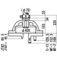 | 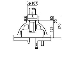 | 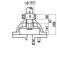 |
| The dimensions in the above figure are part of an attachable drilling machine and screw spindle. Detailed dimensions regarding actual model to be installed may be different, so please contact our service center. | ||
Related Products
-
JTEKT T Series Drive Shaft For Steel Production/ Industrial Equipment
-
Obishi Keiki Seisakusho Attachment for Gear Deflection Measurement ( SH Type )
-
Vessel No.GT-NT10-6 Slide-Off Air Nipper Vertical-type
-
Gentos SB-225 Head Strap (Size L)
-
DIJET MSN-M10/M12/M16 Series Endmill Carbide Shank Holder
-
Chiyoda Tsusho M4/6 MALE CONNECTOR[METAL BODY]


