Japan, KONAN ELECTRIC, Rotary Actuator
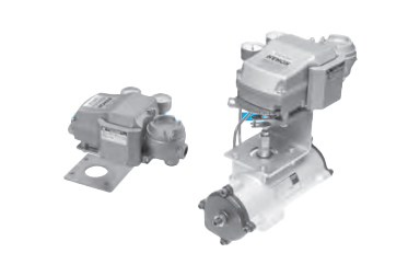
KONAN TA2 Series Rotary Actuator With Pneumatic-Pneumatic Positioner Single-Acting Type
Product Made In Japan
Manufacturer: KONAN ELECTRIC
Model: TA2 Series
This type is equipped with a compact electric pneumatic positioner, which precisely controls the rotating angle of the actuator. We provide two options available:CW Type turns clockwise to increment the signal pressure, and the CCW type turns vice versa.
Specifications
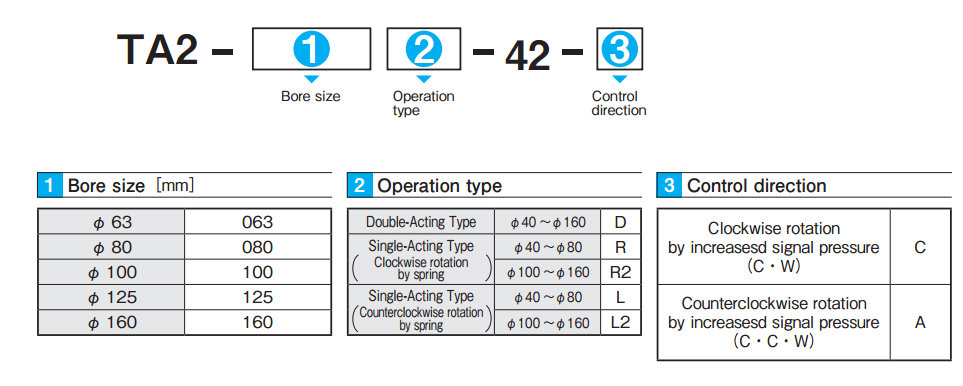
| Bore size[mm] | φ 63 | φ 80 | φ 100 | φ 125 | φ 160 |
| Operating fluid | Compressed air | ||||
| Operating pressure | 0.3 〜 0.7MPa | ||||
| Proof pressure | 1.05MPa | ||||
| Operating temperature | -5〜 60℃(In case of 5℃ or less, ensureto be removed any water contained for prevention of freezing.) | ||||
| Output torque | Please refer to the“Table of Output Torque”(P21 〜 P23) (The load torque is recommended not to exceed 50% of the valve in the output torque table.) | ||||
| Rotating angle | 90° | ||||
| Angle adjustment range | ± 5°both end | ||||
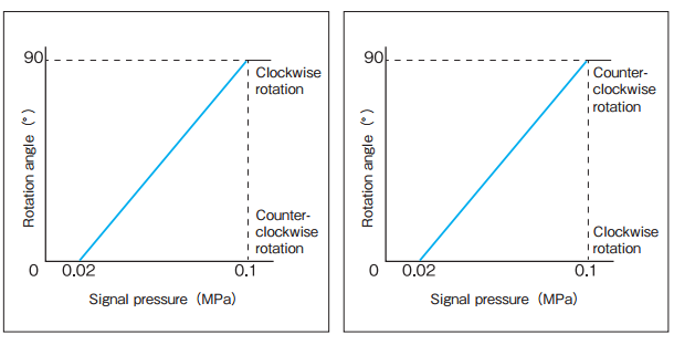
Characteristics of the Positioner
| Input signal | 0.02 〜 0.1MPa |
| Cam characteristics | Linear characteristics |
| Linearity | ± 5% F.S |
| Hysteresis | 2% F.S |
| Repeatability | 3% F.S |
| Sensitivity | 3% F.S |
| Seismic capacity | 1% F.S |
| Air consumption | 10L/min〔ANR〕(SUP 0.4MPa, Output pressure 75%) |
| Structure | Dust proof and drip proof |
| Main component material | Body, Cover:Aluminum |
Model Code
Operating principle
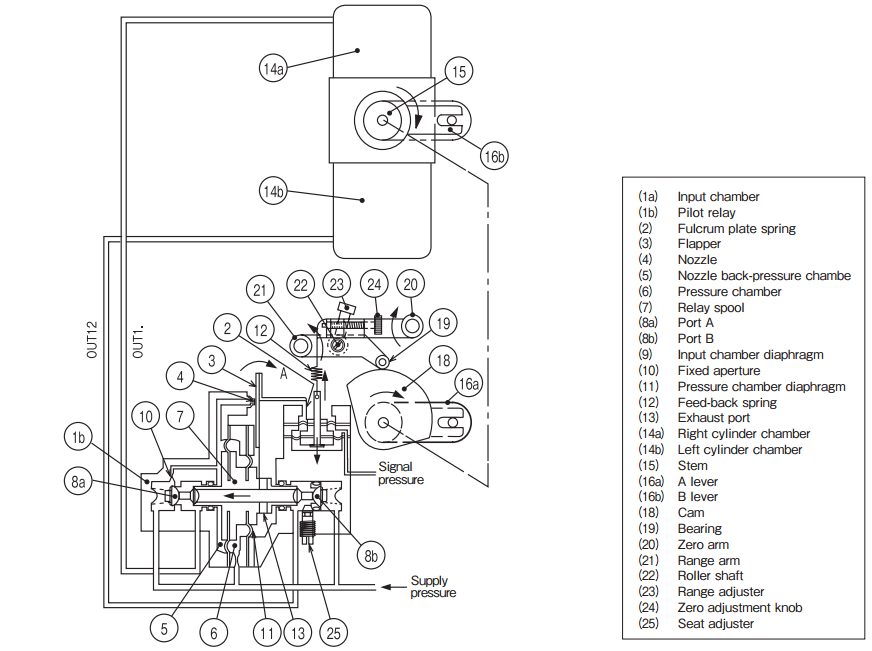
When input signal is applied to the input chamber (1a), the flapper moves in arrow A direction around the fulcrum plate spring (2). This movement causes the flapper (3) to be separated from the nozzle (4) and the pressure of the nozzle back-pressure chamber (5) to decrease, the balance with the pressure chamber (6) to be lost, and relay spool (7) to push the port A (8a) to open the air-intake valve seat. At the same time, in the port B (8b), the air-intake valve seat of the relay spool (7) is closed and the exhaust valve is opened. Supply pressure is fed from the OUT1. to the right cylinder chamber (14a) and from the OUT2. to the left cylinder chamber (14b) and finally vented to atmosphere via the exhaust port (13) to lower the stem (15). This movement is transferred to the B lever (16b), A lever (16a), cam (18), zero arm (20) and range arm (21) to extend the feed-back spring (12) and move until the spring tensile strength balances with the output of the input chamber. Accordingly, change in opening of the stem (15) in proportion to the input signal pressure is obtained. In balanced conditions at the point indicated by the signal, the respective air-intake valve seat and exhaust valve seat of the OUT1. and OUT2. are returned to the neutral position. In the conditions where loads are not applied to the right and left cylinder chambers, the pressure is set at the balance pressure (approx. 75% of supply pressure).
Characteristics
Dimensions of the Positioner
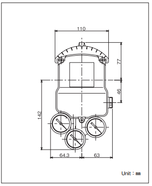
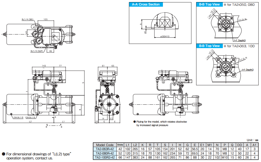
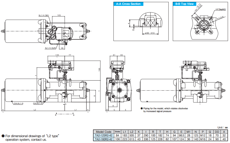
External Dimensions
〈φ 63・80・100〉
〈φ 125・160〉
- Kouei is Distributor/Agent of KONAN.
- Other items of KONAN.
- Request the quotation for KONAN.
Related Products
-
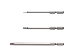
Vessel No.N TORX Bit
-
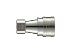
NAC – SP-V TYPE Stainless steel (SUS304) Socket Quick Couplings
-
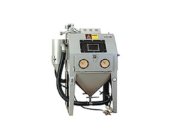
Ascon BS-1/BS-2 General-purpose manual machine (suction type) Blast Cabinet
-
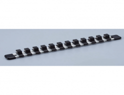
TONE SH14 Socket Holder (Aluminium Type)
-
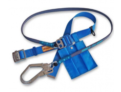
Fujii Denko G-590 (G-cut) Industrial Safety Belt
-
Chiyoda Kogyo EX-150 / EX-150L / EX-150F CNC Tube Bender
REQUEST QUOTATION

PAYMENT

LINK


