- Home
- Products
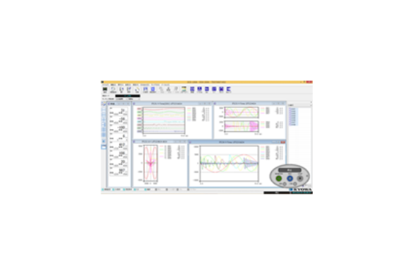
- Kyowa DCS-100A Dynamic Data Acquisition Software DCS-100A Series Dynamic Data Acquisition Software
Japan, Kyowa Electronic Instruments Co., Ltd.
Kyowa DCS-100A Dynamic Data Acquisition Software DCS-100A Series Dynamic Data Acquisition Software
Made in Japan
Manufacturer: Kyowa Electronic Instruments Co., Ltd.
Model: DCS-100A Dynamic Data Acquisition Software
- Monitor
measurement data in a variety of graph and numeric windowsAcquire
efficiently The DCS-100A allows you to easily set various conditions interactively and monitor measurement data in a variety of graph and numeric windows, enabling you to efficiently acquire the data you need.
The instruments to be controlled are CTRS-100 Series, EDX-10 Series, EDX-200A, EDX-5000A and PCD-400/430A, UCAM-550A, NTB-500C.
Feature
● Common operability independent of the measuring instrument to be controlled The basic operation method does not depend on the instrument to be controlled, so it can be easily used even if the instrument is changed ● Y-Time, X-Y, bar meter, circle meter, numerical value display is possible ● Japanese / English Windows compatible ●From setting measurement conditions to acquisition and data playback This software alone enables measurement condition setting, acquisition, data recovery, data playback, and file conversion. For analyzing acquired data, the optional DAS-200A is available ● Acquisition of large amounts of data using a PC hard disk is possible ● Automatic retrieval of acquired data is possible ● Easy operation is possible with toolbars, function keys, and operation panel ● During data playback, Can be converted from Republican Standard Data File (KS2) to CSV and Excel formats.
Common Specifications
Operating environment
| OS | Runs in WOW8 (Windows 1-bit On Windows 10-bit) environment for Windows 11.32, Windows 64, Windows 64 Japanese/English, and 64/32-bit compatible 64-bit OS.®®® |
|---|---|
| CPU | Intel Core i5 2GHz or higher recommended |
| memory | If the OS is 32-bit, 2GB or moreIf the OS is 64-bit, 4GB or more |
| display | Resolution 1024×768 or higher |
monitor
| Time Series Graph | The X axis is the time axis, the Y axis is the physical quantity, and up to 16 channels can be displayed, 1~1 graphs can be displayed in one window. |
|---|---|
| Time series (all channels) graph | The X axis is the time axis and the Y axis is the physical quantity, and all measurement channels can be displayed with the same color line. |
| Time Series (DIV) Graph | The X axis is the time axis and the Y axis is a physical quantity, and up to 16 channels can be displayed. The 0 point position of the display channel can be placed at any position on the Y-axis divider. |
| X-Y Graph | Up to 8 channel combinations for both X and Y axes can be displayed graphically |
| Bar Graph | Up to 1 channels can be displayed in one graph32~1 graphs can be displayed in one windowPeak hold can be displayed (peak value can be displayed numerically) |
| Yen Meter | Any one channel can be displayed with a circle meter |
| Bar Meter | Any single channel can be displayed with a vertical or horizontal meter |
| Numeric display | Arbitrary 1-channel display, optional 16-channel display, All channel display (maximum and minimum values for each channel can be displayed) |
| Input overdisplay | Input over-channel numbers can be displayed in red |
| Graph Scale | The Y axis of autoscale/full-scale display time series graphs can be switched by 1-axis, 2-axis, and channel on the Y axis of time series graphs, the X-Y axis of X-Y graphs, and the Y axis of Bar graphs. |
| Screen display color | Can be changed arbitrarily on a window-by-window basis |
| Titles,Labels | Title, X-axis, Y-axis label can be set arbitrarily |
| Number of simultaneous displays | Numeric windows: Up to 32, Graph windows: Up to 32 numeric and graph windows can be displayed up to 64 (including the number of numerical and graph windows displayed in data confirmation) * Depending on the CPU and memory of the PC, the maximum number may not be displayed. |
| Witness lines | Arbitrary auxiliary lines can be displayed on the X and Y axes of time series graphs, X-Y graphs, and Bar graphs (up to 4 auxiliary lines can be displayed for each X and Y axes). |
| Comparison data display | Comparison data (KS2 data acquired in the past) can be displayed in a time series graph (all channels, excluding DIV) and X-Y graphs, and the monitor data can be compared with the previous data. The maximum data file size that can be displayed is 10MB. If the data exceeds 10MB, the first 10MB of data can be displayed. |
| Dual display support | Numeric and graph windows can be moved to sub-display |
Channel conditions, measurement conditions
| Channel conditions, measurement conditions | According to the specifications of each control device |
|---|---|
| TEDS Information Reading | Read TEDS information and automatically set channel conditions (TEDS compatible devices only) |
| Saving and reading measurement condition files | Set measurement conditions can be saved and loaded. |
Preferences
| Data file destination | Save to media on each control device. Depending on the sampling frequency and the number of measurement channels, it is possible to save directly to a PC folder without saving to the media of each control unit. |
|---|---|
| Automatic file recovery | After the measurement is completed, the acquired data file is automatically retrieved to the PC folder. |
| Automatic file conversion | After the measurement is completed, the system automatically converts to any format (CSV format, XLS format, XLSX format, RPC III format). |
| Arbitrary unit setting | Three types of units can be registered arbitrarily by the user. |
| PAUSE Capabilities During Acquisition | Configurable to disable/not |
Data
| Storage format | Saved in the Republican Standard File Format (KS2). |
|---|---|
| File Binding | Data files acquired by each control device by synchronous operation are combined at the time of retrieval and converted into a single data file. |
Data Verification
| Time Series Graph | The X axis is the time axis, the Y axis is the physical quantity display, and up to 16 channels can be displayed, and 1~1 graphs can be displayed in one window. |
|---|---|
| Time Series (DIV) Graph | The X axis is the time axis and the Y axis is a physical quantity, and the 16 point position of the display channel can be changed to any position on the Y-axis dividing line. |
| X-Y Graph | Up to 8 channel combinations for both X and Y axes can be displayed graphically |
| Numeric display | List |
| Graph Scale | Autoscale and full-scale display are possible on the Y axis of a time series graph, the X and Y axes of an X-Y graph, and the Y axis of a Bar graph. The Y axis of the time series graph can be switched by 1-axis, 2-axis, and channel. |
| Screen display color | Can be arbitrarily changed to graph units |
| Titles,Labels | Title, X-axis, Y-axis label can be set arbitrarily. |
| Number of simultaneous displays | Numeric windows: Up to 32, Graph windows: Up to 32 numeric and graph windows can be displayed up to 64 (including the number of numerical and graph windows displayed on the monitor) * Depending on the CPU and memory of the PC, the maximum number may not be displayed. |
| Viewable datafile size | The maximum data file size that can be displayed in the numeric/graph window is 10MB. When the size exceeds 10MB, an arbitrary range of 10MB can be displayed by setting the display range. |
| File Conversion | Extract files from arbitrary ranges and channels, and convert them to arbitrary formats (CSV format, XLS format, XLSX format, RPC III format) |
| Witness lines | Arbitrary auxiliary lines can be displayed on the X and Y axes of time series graphs, XY graphs, and Bar graphs. (Up to 4 lines can be displayed for each X and Y axis) |
| Maximum, minimum, and average values | The maximum, minimum, and average values of the graph display range can be displayed in a time series graph (can be displayed when the number of display channels is 2 channels or less). |
| Dual display support | Numeric and graph windows can be moved to the sub-display. |
EDX-100A Control Specifications
| Number of connected devices | Up to 8 units (up to 256 channels) |
|---|---|
| interface | LAN,USB |
| Acquisition | Measurement data is saved as a KS100 file on the CF card of the EDX-2A and in the PC folder. |
| Channel conditions | Measurement ON/OFF, Mode, Range, High-pass Filter, Low-Pass Filter, Balance ON/OFF, CAL Range, CAL ON/OFF, Calibration Coefficient, Offset, Unit, Channel Name, Measurement Range, Rated Capacity, Rated Output, Number of Digits Displayed, Internal Sensitivity Registration ON/OFF, Offset Zero ON/OFF (Display items can be selected arbitrarily) |
| TEDS compliant | Read TEDS information and automatically set channel conditions |
| Setting and reading parameters | EDX-100A’s internal parameters can be read and set |
| File Recovery | KS100 file recovery in EDX-2A CF card from PC via LAN or USB by inserting the CF card into the PC |
| File deletion | Delete KS100 files from a PC via LAN or USB to the CF card of the EDX-2A |
| Preferences | |
| Hardware configuration settings | Set the number of connected devices and device names. Hardware configuration can be loaded from the EDX-100A. |
| Communication check | Load the EDX-100A version. |
| EDX IP Address Settings | Set to EDX-100A via LAN or USB from a PC. Saving the IP address configuration file to the CF card. |
| Equipment check | The front LED of the EDX-100A can be lit. |
| other | Oscillator switching (internal, external), operation beep |
Measurement conditions when saving measurement data to the CF card of the EDX-100A
| sampling frequency | 1Hz~100kHz(1-2-5 series, 2nseries, external clock) *Limited by the number of measurement channels. |
|---|---|
| Acquiring/File Size | Up to 2GB * The number of data that can be acquired depends on the number of measurement channels. |
| Measurement mode | Manual, Manual (Specify the number of acquired data), Interval, Analog trigger, External trigger, Composite trigger |
| Manual measurement | Acquire between REC and STOP or up to the specified number of data from REC by specifying the number of acquired data. |
| Interval measurement | Acquisition is performed automatically by setting the acquisition start time and acquisition interval. |
| Trigger measurement | Start/stop acquisition according to the set trigger conditions. |
| Common trigger conditions | |
| Termination Trigger | Configurable. |
| Delay amount | The maximum 262144 data * delay for both start and end varies depending on the number of measurement channels. |
| Analog trigger conditions | |
| Trigger Channel | Any 1 channel of master EDX |
| Trigger Level | Set in physical quantities. |
| Trigas rope | Standing Up and Falling |
| External Trigger Conditions | |
| Trigas rope | Standing Up and Falling |
| Compound trigger conditions | |
| Trigger Source | Select from analog channels (any 2 channels of master EDX) and external triggers. Trigger source can be logically determined by AND/OR. |
| Trigger Level | Set in physical quantities. |
| Trigas rope | Standing Up and Falling |
Measurement conditions when saving measurement data in a PC folder
| sampling frequency | 1Hz~100kHz(1-2-5 series, 2nseries, external clock) |
|---|---|
| Acquiring/File Size | Acquire up to hard disk capacity. |
| Measurement mode | Manual, Manual (Specify the number of acquired data), Interval, Analog Trigger |
| Manual measurement | Acquire between REC and STOP or up to the specified number of data from REC by specifying the number of acquired data. |
| Interval measurement | Acquisition is performed automatically by setting the acquisition start time and acquisition interval. |
| Analog trigger measurement | Start/stop acquisition according to the set trigger conditions. |
| Termination Trigger | Configurable. |
| Delay amount | The maximum 262144 data * delay for both start and end varies depending on the number of measurement channels. |
| Trigger Channel | Optional 1 channel |
| Trigger Level | Set in physical quantities. |
| Trigas rope | Standing Up and Falling |
| Static Measurements | Each time acquisition starts, the measurement data after moving average processing is additionally saved in one CSV format file. *Available when the measurement mode is manual or international. |
| Repeated Acquisition | In long-term acquisition, save to a KS2 file at a certain number of data (at regular intervals). *Available when the measurement mode is manual (number of acquired data specified). |
EDX-10 Series Control Specifications
| Number of measuring unit connections | Up to 4 units (up to 16 channels) |
|---|---|
| interface | USB |
| Acquisition | Measurement data is saved as a KS2 file in a PC folder. |
| Channel conditions | Measurement ON/OFF, Mode, Range, Lowpass Filter, Balance, Calibration Factor, Offset, Unit, Channel Name, Measurement Range, Rated Capacity, Rated Output, Number of Digits Numeric, Upper Check Value, Lower Check Value (Display items can be selected arbitrarily) |
| sampling frequency | 1Hz~20kHz (1-2-5 series) *Limited by number of measurement channels |
| Measurement mode | Manual, Manual (Specify the number of acquired data), Interval, Analog Trigger |
| Manual measurement | Acquire between REC and STOP or up to the specified number of data from REC by specifying the number of acquired data. |
| Interval measurement | Acquisition is performed automatically by setting the acquisition start date and time and the acquisition interval. |
| Analog trigger measurement | Start/stop acquisition according to the set trigger conditions. |
| Trigger Conditions | |
| Termination Trigger | Configurable |
| Delay amount | The maximum 262144 data/channel * delay for both start and end varies depending on the number of measured channels. |
| Trigger Channel | Optional 1 channel |
| Trigger Level | Set by physical quantity. |
| Trigas rope | Standing Up and Falling |
| Static Measurements | Each time acquisition starts, the measurement data after moving average processing is additionally saved in one CSV format file. *Possible when the measurement mode is manual or international |
| Repeated Acquisition | Stored in a KS2 file at a certain number of data (at regular intervals) for long-term acquisition. *Available when the measurement mode is manual (number of acquired data specified) |
Preferences
| Hardware configuration settings | Device name and measurement unit setting. The EDX-10B can be set as a device name. Hardware configuration can be loaded from the EDX-10B. |
|---|
EDX-200A Control Specifications
| Number of connected devices | Up to 8 units (up to 256 channels) |
|---|---|
| interface | LAN,USB |
| Acquisition | Measurement data is saved as a KS200 file on the CF card of the EDX-2A and in the PC folder. |
| Channel conditions | Measurement ON/OFF, Mode, Range, High-pass Filter, Low-Pass Filter, Balance ON/OFF, CAL Range, CAL ON/OFF, Calibration Factor, Offset, Unit, Channel Name, Measurement Range, Number of Digits, Rated Capacity, Rated Output, Upper Check Value, Lower Check Value, Internal Sensitivity Registration ON/OFF, Offset Zero ON/OFF, Digital Filter (High Pass, Low pass can be set at any cutoff frequency), sampling frequency (dual sampling high-speed, low-speed, high-speed + low-speed can be selected) (display items can be selected arbitrarily) |
| TEDS compliant | Read TEDS information and automatically set channel conditions. |
| Dual Sampling | High/low speed sampling data can be displayed in numerical and graph windows. High-speed/low-speed sampling data is saved in separate files. |
| Setting and reading parameters | EDX-200A internal parameters can be read and set. |
| File Recovery | Recover KS200 files from a PC via LAN or USB on the CF card of the EDX-2A. |
| File deletion | Deleted KS200 files from a PC via LAN or USB on the EDX-2A’s CF card. |
| CF Card Format | The EDX-200A CF card can be formatted from a PC via LAN or USB. |
| Preferences | |
| Hardware configuration settings | Set the number of connected devices and device names. Hardware configuration can be loaded from the EDX-200A. |
| Communication check | Load the EDX-200A version. |
| EDX IP Address Settings | Set to EDX-200A via LAN or USB from a PC. Saving the IP address configuration file to the CF card. |
| Equipment check | The front LED of the EDX-200A can be lit. |
| other | Oscillator switching (internal, external), operating beep, balanced specification value, AD data format (16/24-bit), synchronous operation mode (choice of using or not using synchronous cable) |
| Option card support | ECAN-40A CAN data acquisition (Note 1) DIO setting (Note 3) ETIM-40A Interval (GPS synchronization) measurement (Note 1), (Note 2) Point zero (manual) measurement (Note 1), (Note 2)
GPS data acquisition (Note 1), (Note 2) DIO setting (Note 3) EGPC-40A CAN data acquisition (Note 1) Interval (GPS synchronization) measurement (Note 1), (Note 2) Point zero (manual) measurement (Note 1), (Note 2) GPS data acquisition (Note 1), (Note 2) DIO setting (Note 3) Note 1: Data must |
| CAN Data Acquisition | Up to 1 channels of CAN data can be acquired per unit (CAN data is saved as E512A files on the EDX-200A CF card) |
| Point zero (manual) measurement | Manual measurements can be performed on multiple EDX-200A, and acquisition can be started at zero seconds (when ms is 0) using time data received from GPS satellites. |
| Interval (GPS-synchronous) measurement | Using the time data received from GPS satellites, it is possible to acquire data synchronized at the same time on multiple EDX-200A by matching the acquisition start time. |
| GPS Data Acquisition | GPS data (latitude, longitude, speed, direction, etc.) can be monitored and acquired. GPS data is saved as an NMEA format file on the CF card of the EDX-200A. 「 |
| DIO Settings | |
| Number of input/output points | Up to 8 points |
| Input/output settings | Digital input, digital output, and remote control input can be set for each bit. |
Setting conditions for saving measurement data to the CF card of the EDX-200A
| sampling frequency | 1Hz~100kHz(1-2-5 series, 2nseries, external clock) *Limited by the number of measurement channels. Dual sampling support (high/low speed sampling can be set) |
|---|---|
| Acquiring/File Size | Up to 4GB |
| Measurement mode | Manual, Manual (Specify the number of acquired data), Interval, Analog trigger, External trigger, Composite trigger |
| Manual measurement | Acquire between REC and STOP or up to the specified number of data from REC by specifying the number of acquired data. |
| Interval measurement | Acquisition is performed automatically by setting the acquisition start time and acquisition interval. |
| Trigger measurement | Start/stop acquisition according to the set trigger conditions. |
| Common trigger conditions | |
| Termination Trigger | Configurable. |
| Delay amount | The maximum 262144 data * delay for both start and end varies depending on the number of measurement channels. |
| Analog trigger conditions | |
| Trigger Channel | Any 1 channel of master |
| Trigger Level | Set by physical quantity. |
| Trigas rope | Standing Up and Falling |
| External Trigger Conditions | |
| Trigas rope | Standing Up and Falling |
| Compound trigger conditions | |
| Trigger Source | Select from analog channels (any 4 channels of master EDX), external triggers, and manual triggers. |
| Trigger Level | Set in physical quantities. |
| Trigas rope | Standing Up and Falling |
| Repeated Acquisition | In long-term acquisition, save to a KS2 file at a certain number of data (at regular intervals). *Available when the measurement mode is manual (number of acquired data specified). |
Measurement conditions when saving measurement data in a PC folder
| sampling frequency | 1Hz to 100kHz (1-2-5 series, 2nseries, external clock) |
|---|---|
| Acquiring/File Size | Acquire up to hard disk capacity. |
| Measurement mode | Manual, Manual (Specify the number of acquired data), Interval, Analog Trigger |
| Manual measurement | Acquire between REC and STOP or up to the specified number of data from REC by specifying the number of acquired data. |
| Interval measurement | Acquisition is performed automatically by setting the acquisition start time and acquisition interval. |
| Analog trigger measurement | Start/stop acquisition according to the set trigger conditions. |
| Termination Trigger | Configurable. |
| Delay amount | The maximum 262144 data * delay for both start and end varies depending on the number of measurement channels. |
| Trigger Channel | Optional 1 channel |
| Trigger Level | Set in physical quantities. |
| Trigas rope | Standing Up and Falling |
| Static Measurements | Each time acquisition starts, the measurement data after moving average processing is additionally saved in one CSV format file. *Available when the measurement mode is manual or international. |
| Repeated Acquisition | In long-term acquisition, save to a KS2 file at a certain number of data (at regular intervals). *Available when the measurement mode is manual (number of acquired data specified). |
NTB-500C Control Specifications
| Number of connected devices | Up to 8 (up to 64 channels) |
|---|---|
| interface | Uses a CAN *USB/CAN converter (LEAFLIGHT HS V2). |
| Acquisition | Measurement data is saved as a KS2 file in a PC folder. |
| Channel conditions | Measurement ON/OFF, Mode, Range, ZERO, Calibration Factor, Offset, Unit, Channel Name, Measurement Range, Rated Capacity, Rated Output, Number of Digits Displayed Numerically, Upper Check Value, Lower Check Value (Display items can be selected arbitrarily) |
| sampling frequency | 1Hz~1kHz *Limited depending on communication cable length and number of measurement channels. |
| Measurement mode | manual, manual (setting the number of acquired data), intervalu, analog trigger |
| Manual measurement | Acquire between REC and STOP or up to the specified number of data from REC by specifying the number of acquired data. |
| Interval measurement | Acquisition is performed automatically by setting the acquisition start date and time and the acquisition interval. (The acquisition interval can be changed for each STEP number 5 and STEP) |
| Analog trigger measurement | Start/stop acquisition according to the set trigger conditions. |
| Termination Trigger | Configurable |
| Delay amount | Maximum 262144 data for both start and end * The delay amount varies depending on the number of measurement channels. |
| Trigger Channel | Optional 1 channel |
| Trigger Level | Set in physical quantities. |
| Trigas rope | Standing Up and Falling |
| TEDS compliant | Read TEDS information and automatically set channel conditions. |
| Refill process | When a displacement meter is used, it is possible to change the data after movement to the data before the move. |
| Static Measurements | Each time acquisition starts, the measurement data after moving average processing is additionally saved in one CSV format file. * Available when the measurement mode is manual or international. |
| Repeated Acquisition | In long-term acquisition, save to a KS2 file at a certain number of data (at regular intervals). * Available when the measurement mode is manual (number of acquired data specified). |
Preferences
| Hardware configuration settings | Number of units connected, communication cable length, device name, measurement unit settings. Hardware configuration can be read from NTB-500A/C. |
|---|
UCAM-550A Control Specifications
| Number of connected devices | Up to 6 units (maximum 300 channels) Standard specification maximum 20 units (maximum 1000 channels) When DCS-106A (sold separately) is installed |
|---|---|
| interface | LAN |
| Acquisition | Measurement data is saved as a KS2 file in a PC folder. |
| sampling frequency | 1,2,10,20,50Hz |
| Measurement mode | manual, manual (setting the number of acquired data), intervalu, analog trigger |
| Measurement Functions | Measure: Measured value = Sensor output value – Initial value Original: Measured value = Sensor output value |
| Calibration coefficient calculation | ON/OFF setting calibration factor calculation for all channels at once: calibration factor + offset × measured value |
| Channel conditions | Measurement, mode, range, calibration factor, offset, unit, initial value, channel name, measurement range, rated capacity, rated output, number of digits displayed numerically, upper check value, lower limit check value (display items can be selected arbitrarily) |
| Initial value setting | Measure the initials of each sensor |
| Manual measurement | Acquire between REC and STOP or up to the specified number of data from REC by specifying the number of acquired data. |
| Interval measurement | Acquisition is performed automatically by setting the acquisition start time and acquisition interval. |
| Analog trigger measurement | Start/stop acquisition according to the set trigger conditions. (Trigger level is fixed) |
| Termination Trigger | Configurable |
| Delay amount | Up to 3000 data for both start and end |
| Trigger Channel | Optional 1 channel |
| Trigger Level | Set by physical quantity |
| Trigas rope | Standing Up and Falling |
| Refill process | When a displacement meter is used, it is possible to change the data after movement to the data before the move. |
| Static Measurements | Each time acquisition starts, the measurement data processed by moving average is additionally saved in one CSV format file. *Possible when the measurement mode is manual or international |
| Burnout check | Burnout check possible (USM-51B/52B only) |
| TEDS compliant | Import TEDS information and automatically set channel conditions (USM-51B/52B only) |
| Setting and reading parameters | Capable of reading and configuring the internal parameters of the UCAM-550A |
Preferences
| Hardware configuration settings | Measurement unit configuration can be read from UCAM-550A with the number of connected units, device name, and measurement unit settings . |
|---|---|
| Communication check | Loading the UCAM-550A Version |
PCD-400A PCD-430A Control Specifications
| Number of measuring unit connections | Up to 4 units (up to 16 channels) |
|---|---|
| interface | USB |
| Acquisition | Measurement data is stored on a PC hard disk. (saved as KS2 file) |
| Channel conditions | Measurement ON/OFF, Strain mode, Range, Low-pass filter, High-pass filter, Balance ON/OFF, Calibration factor, Offset, Gauge rate, Unit, Channel name, Measurement range, Decimal places, Rated capacity, Rated output, Upper limit check value, Lower limit check value, Offset zero ON/OFF (display items can be selected arbitrarily) |
| sampling frequency | 1Hz~10kHz(1-2-5 series) |
| Measurement mode | Manual, Manual (Specify the number of acquired data), Interval, Analog Trigger |
| Manual measurement | Acquire between REC and STOP or up to the specified number of data from REC by specifying the number of acquired data. |
| Interval measurement | Acquisition is performed automatically by setting the acquisition start time and acquisition interval. |
| Analog trigger measurement | Start/stop acquisition according to the set trigger conditions. (Trigger level value is fixed) |
| Trigger Conditions | |
| Termination Trigger | Configurable |
| Delay amount | The maximum of 640000 data/channel * delay amount for both start and stop varies depending on the number of measurement channels. |
| Trigger Channel | Optional 1 channel |
| Trigger Level | Set by physical quantity |
| Trigas rope | Rise/fall |
| Static Measurements | Each time acquisition starts, the measurement data after moving average processing is additionally saved in one CSV format file. *Possible when the measurement mode is manual or international |
| Repeated Acquisition | In long-term acquisition, it is saved in a KS2 file at a certain number of data (every certain time). *Available when the measurement mode is manual (number of acquired data specified) |
Preferences
| Hardware configuration settings | Unit name, unit settings. Unit name can be set to PCD-400A/430A. The number of connected devices can be read from the PCD-400A/430A. |
|---|---|
| Automatic data file conversion | Automatic file conversion (CSV format, XLS format, XLSX format, RPC III format) is performed automatically at the end of the measurement. |
| Arbitrary unit setting | Three types of units can be registered arbitrarily by the user. |
EDX-5000A Control Specifications
| Number of connected devices | Up to 10 units (max. 800 analog channels, 10 digital channels) *Synchronous operation is possible with EDX-5000A + EDX-3000B or EDX-5000A + EDX-200A. Up to 200 units in synchronous operation with the EDX-8A. |
|---|---|
| interface | LAN(100BASE-TX, 1000BASE-T) |
| Acquisition | Measurement data is saved as a KS5000 file on the EDX-2A data drive and PC folder. |
| Channel conditions | Measurement ON/OFF, Mode, Range, High-pass Filter, Low-Pass Filter, Balance ON/OFF, CAL Range, CAL ON/OFF, Calibration Factor, Offset, Unit, Channel Name, Measurement Range, Rated Capacity, Rated Output, Number of Digits, Upper Check Value, Lower Check Value, Internal Sensitivity Registration ON/OFF, Offset Zero ON/OFF, Digital Filter (High Pass, Low pass can be set at any cutoff frequency) (display items can be selected arbitrarily) |
| TEDS compliant | Read TEDS information and set it automatically to channel conditions. |
| Setting and reading parameters | EDX-5000A internal parameters can be read and set. |
| File Recovery | File recovery in EDX-5000A data drive. (KS2,E4A,NMEA) |
| File deletion | Deletion of files in EDX-5000A data drive. (KS2,E4A,NMEA) |
| Preferences | |
| Hardware configuration settings | Set the number of connected devices and device names. |
| Communication check | Check EDX-5000A connection status and display version. |
| Equipment check | The front LED of the EDX-5000A can be lit. |
| other | Oscillator switching (internal, external), operating beep, balance standard value, AD data format (16/24-bit) |
| DIO Settings | |
| Number of input/output points | Digital input, digital output, and remote control input can be set every 8 bits. |
Measurement conditions when saving measurement data to EDX-5000A data drive
| sampling frequency | 1Hz~200kHz(1-2-5 series, 2nSeries, external clock) *Limited by the number of measurement channels and the number of connected channels. |
|---|---|
| Acquiring/File Size | Acquire up to internal disk space. |
| Measurement mode | Manual, Manual (Specify the number of acquired data), Interval, Analog trigger, External trigger, Composite trigger |
| Manual measurement | Acquire between REC and STOP or up to the specified number of data from REC by specifying the number of acquired data. |
| Interval measurement | Acquisition is performed automatically by setting the acquisition start time and acquisition interval. |
| Trigger measurement | Start/stop acquisition according to the set trigger conditions. |
| Common trigger conditions | |
| Termination Trigger | Configurable. |
| Delay amount | The maximum 4194304 data * delay for both start and end varies depending on the number of measurement channels. |
| Analog trigger conditions | |
| Trigger Channel | Any 1 channel of master EDX |
| Trigger Level | Set by physical quantity. |
| Trigas rope | Standing Up and Falling |
| Digital trigger conditions | |
| Trigger Bits | Any 1 bit of master EDX |
| Trigger Level | 0,1 |
| External Trigger Conditions | |
| Trigas rope | Standing Up and Falling |
| Compound trigger conditions | |
| Trigger Source | Select from analog channels (any 4 channels of master EDX), external triggers, ECAN triggers, and manual triggers. Trigger source can be logically determined by AND/OR. |
| Trigger Level | Set in physical quantities. |
| Trigas rope | Standing Up and Falling |
| Repeated Acquisition | In long-term acquisition, save to a KS2 file at a certain number of data (at regular intervals). *Available when the measurement mode is manual (number of acquired data specified). |
| When EGPC-50A is embedded | |
| CAN Data Acquisition | Up to 1 channels of CAN data can be acquired per unit. (CAN data is saved as an E512A file on the EDX-5000A data drive.) ) |
| Point zero (manual) measurement | Using the time data received from GPS satellites, it is possible to start manual measurement at zero second time (time when ms is 0). |
| Interval (GPS sync) measurement | Using the time data received from GPS satellites, it is possible to start interval measurement at zero second time (time when ms is 0). |
| GPS Data Acquisition | GPS data (latitude, longitude, speed, direction, etc.) can be monitored and acquired. GPS data is saved as NMEA files on the EDX-5000A data drive. |
Measurement conditions when saving measurement data in a computer folder
| sampling frequency | 1Hz~10kHz(1-2-5 series,2nSeries, external clock) *Limited by the number of measurement channels and the number of connected channels. |
|---|---|
| Acquiring/File Size | Acquire up to storage disk space. |
| Measurement mode | Manual, Manual (Specify the number of acquired data), Interval, Analog Trigger |
| Manual measurement | Acquire between REC and STOP or up to the specified number of data from REC by specifying the number of acquired data. |
| Interval measurement | Acquisition is performed automatically by setting the acquisition start time and acquisition interval. |
| Analog trigger measurement | Start/stop acquisition according to the set trigger conditions. |
| Termination Trigger | Configurable |
| Delay amount | The maximum 4194304 data * delay for both start and end varies depending on the number of measurement channels. |
| Trigger Channel | Optional 1 channel |
| Trigger Level | Set in physical quantities. |
| Trigas rope | Standing Up and Falling |
| Repeated Acquisition | In long-term acquisition, save to a KS2 file at a certain number of data (at regular intervals). *Available when the measurement mode is manual (number of acquired data specified). |
CTRS-100A Control Specification
| Number of connected devices | Up to 4 units (up to 128 analog channels) |
|---|---|
| interface | USB (USB2.0 High Speed), Ethernet (10/100BASE-T) *Ethernet connection requires a separate synchronization unit and dedicated communication cable. |
| Acquisition | Measurement data is stored on the CTRS-100A’s SD card and PC folder. When saving the CTRS-100A SD card, save as a KS3 file. When saving to a PC folder, save as a KS3 file or a KS2 file (01.06). |
| Channel conditions | Measurement ON/OFF, Mode, Range (Arbitrary Range Input Supported), High-Pass Filter, Low-Pass Filter, Balanced ON/OFF/NONE, input resistance check ON/OFF, Calibration factor, Offset, Cable correction value, Offset zero value, Unit, Channel name, Measurement range (optional input supported), Rated capacity, Rated output, Number of digits displayed, Upper check value, Lower check value, Zero offset ON/OFF, TEDS user data, TEDS sensor serial number, TEDS sensor model, TEDS ROMID (display items can be selected arbitrarily) |
| TEDS compliant | Read TEDS information and automatically set channel conditions. |
| Input overreset | It is possible to clear the input over judgment. |
| Offset Zero | It is possible to assign the current measurement data to the zero offset value of the analog channel and set the apparent measurement data to zero. |
| Setting and reading parameters | The internal parameters of the CTRS-100A can be read and set. |
| Saving and reading measurement condition files | Measurement conditions, numerical and graph display conditions can be saved and read into a condition file (extension C1H). |
| Saving and loading CTRS-100A condition file | Condition files (extension SET) saved on the CTRS-100A SD card can be read and saved. |
| File Recovery | Recover KS100 and KC3 files from the CTRS-3A SD card. (KS3 files can be recovered by converting them to KS2 files.) ) |
| File deletion | Deleted KS100 and KC3 files in the SD card of CTRS-3A. |
| SD Card Format | CTRS-100A SD card format. |
Preferences
| Hardware configuration settings | Interface selection, number of connected devices, and device name settings. |
|---|---|
| Communication check | CTRS-100A connection status check and version display. |
| Equipment check | The front LED of the CTRS-100A can be lit. |
| other | Remote control unit operation beep, balance standard value, PAUSE ON/OFF, Detailed hardware information display |
When the CAN unit is embedded
| CAN Data Acquisition | Acquire up to 1 messages of CAN data per unit. (CAN data is saved as a KC1024 file.) *In the case of a PC folder, up to one CAN unit to be measured |
|---|---|
| CAN data output | Start output, stop output, interval output, manual output |
Measurement conditions when storing measurement data on the SD card of the CTRS-100A
| sampling frequency | 1Hz~100kHz(1-2-5 series, 2nseries, external clock) *Limited by the number of measurement channels. |
|---|---|
| Number of data that can be acquired | 1000000000 data |
| Measurement mode | Manual, Manual (specify the number of acquired data), Interval, Analog trigger, External trigger, Manual trigger, Composite trigger, CAN trigger*CAN trigger requires a separate CAN unit |
| Manual measurement | Acquire between REC and STOP or up to the specified number of data from REC by specifying the number of acquired data. Acquisition start date and time can be set. |
| Interval measurement | Acquisition is performed automatically by setting the acquisition start time and acquisition interval. |
| Trigger measurement | Start/stop acquisition according to the set trigger conditions. |
| Common trigger conditions | Termination trigger: Configurable. Delay amount: Up to 524288 data for both start and end *The delay amount varies depending on the number of measurement channels. |
| Analog trigger conditions | Trigger channel: Any 1-channel
trigger level of the master: Set by physical quantity. Trigas rope: rising and falling |
| External Trigger Conditions | Trigas rope: rising and falling |
| Manual triggering | |
| Compound trigger conditions | Trigger source: Select from analog channels (any 4 channels of master), external triggers, and manual triggers. Trigger source can be logically determined by AND/OR. Trigger level: Set by physical quantity. Trigas rope: rising and falling |
CAN Trigger Conditions
| Common CAN trigger conditions | Termination trigger: Configurable. Delay amount : End only can be set, maximum 174762 seconds when measurement channel is available, maximum 65535 seconds when no measurement channel is available *Delay amount varies depending on sampling frequency and number of measurement channels. |
|---|---|
| Manual triggering | |
| Analog trigger conditions | Trigger channel: any 1 Signal trigger level: set by physical quantity. Trigas rope: rising and falling |
| Digital trigger conditions | Trigger channel: any 1 Signal trigger bit: any 1 bit of trigger channel Trigas rope: rising, falling, level |
| Compound trigger conditions | Trigger Source Trigger channel (any 8 Signals on the master) Analog trigger and digital trigger can be selected for each trigger channel Trigger sources can be logically determined by AND/OR at once. |
| Repeated Acquisition | In long-term acquisition, save to a KS3 file at a certain number of data (at regular intervals). *Available when the measurement mode is manual (number of acquired data specified). |
|---|---|
| Data | File name, file title, grant rule (file number, acquisition start time), file number (3~5 digits) |
Measurement conditions when saving measurement data in a computer folder
| sampling frequency | 1Hz~100kHz(1-2-5 series, 2nSeries, external clock) *Limited by the number of measurement channels, 2 kHz or less when acquiring CAN data in synchronous operation. |
|---|---|
| Acquiring/File Size | Acquire up to storage disk space. |
| Measurement mode | Manual, Manual (Specify the number of acquired data), Interval, Analog Trigger |
| Manual measurement | Acquire between REC and STOP or up to the specified number of data from REC by specifying the number of acquired data. |
| Interval measurement | Acquisition is performed automatically by setting the acquisition start time and acquisition interval. |
| Analog trigger measurement | Start/stop acquisition according to the set trigger conditions.
Termination trigger: Configurable. |
| Static Measurements | Each time acquisition starts, the measurement data processed by moving average is additionally saved in one CSV format file. *Available when the measurement mode is manual or international. |
| Repeated Acquisition | In long-term acquisition, save to a KS2 file at a certain number of data (at regular intervals). *Available when the measurement mode is manual (number of acquired data specified). |
| Data | File name, file title, grant rule (fixed file number), file number (fixed 4 digits) |
Related Products
-
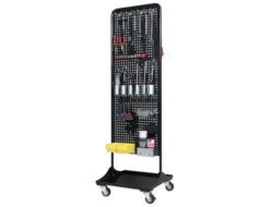
Nagasaki Jack NPW-1A Tool punching wagon
-
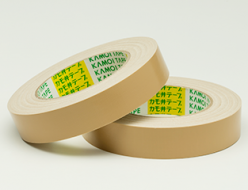
Kamoi Kakoshi No.6000 For Spray Painting, Fabric Adhesive Tape
-
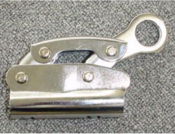
Fujii Denko T-537/R Rope Adjuster (Adjusting Implement)
-
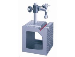
RSK 559 Box V Block With Clamp
-
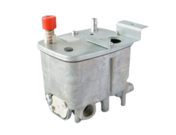
Taisan 320L/320L-V Oil Leveler
-
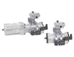
KONAN TA2 Series Rotary Actuator With 5-Port Solenoid Valve and Limit Switch Box Single-Acting Type
REQUEST QUOTATION

PAYMENT

LINK


