Electronic Counters, Line Seiki, Measurement
Line Seiki G90 / G95 Series Large Display Counters
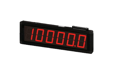
Product Made in Japan
Manufacturer: Line Seiki
Model: G90 Series
G90/G95 Series Large Display Counters
Features
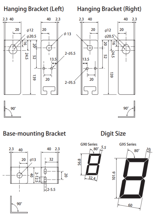
Digit Size
2 sizes (G90: 56.8mm; G95: 101.6mm)
Function
Both hanging brackets and base-mounting brackets are included in all models.
Mounting methods
Counter/Display are selectable in G90-303 and G95-303.
Model

Description
- The G90 Series is a large display electronic counter with an LED digit size of 56.8 x 32.4mm. The G90 Series is available in 6 digits and it can be directly hooked to an input signal source of up to 1kHz count speed.
- The G95 Series is an X-large display electronic counter with an LED digit size of 101.6 x 60mm. The G95 Series is available in 6 digits and it can be directly hooked to an input signal source of up to 1kHz count speed.
- The mode of counting is Add/Subtract and Quadrature.
- The reset is done remotely.
- It has a built-in memory for count value retention in case power is lost.
- The power source is AC100 – 240V and an external power supply of DC12V are available for the sensors.
- Additional features include Decimal Point position, Free Write, and input inhibition.
- The G90 Series and G95 Series hava a very sturdy and heavy-duty casing which can be hanged, base- or wall-mounted.
Application
Production Monitoring
Getting the right information at the right time will streamline your production and will result in higher productivity.
Specification
G90 Series
| Model | G90-301 | G90-303 |
| No. of Digits | 6 (Digit Size : 56.8(H) mm x 32.4(W) mm) | |
| Free Write / Display (25-Pin D-Sub: BCD Input) | – | O |
| Weight | approx. 1.5kg | |
| Models | G90-301 / G90-303 | ||||||||||||
| Display | RED LED Zero Suppressing: 56.8(H) mm x 32.4(W) mm | ||||||||||||
| No.of Digits | 6 | ||||||||||||
| Power | AC100 – 240V / -15% – +10% 50/60Hz | ||||||||||||
| Power Consumption | Approximately 6VA | ||||||||||||
| Input | Non-contact Input: Open Collector Transistor : L < 2V (Sink Current 7mA) Voltage Input: L: 0 – 5V H : 10 – 30V (Input Impedance 1.6KΩ) Contact Input: Relay, Microswitch, etc. (Sink Current 10mA) | ||||||||||||
| Connection | Input : Terminal Screw Power : Terminal Screw BCD * : 25-Pin D-Sub (DB25) Connector | ||||||||||||
| Decimal Point | Selectable through DIP Switch (0.0/0.00/0.000) | ||||||||||||
| Count Speed | Non-contact : 1kHz Contact : 20Hz | ||||||||||||
| Count Mode | 90°Quadrature Input Add/Subtract (Individual) | ||||||||||||
| Pulse Width | Non-contact Input : 500µsec min. Contact Input: 25msec min. (Duty 1:1) | ||||||||||||
| Count Range * | -99999 – +999999 | ||||||||||||
| Display Range * | 0 – 999999 | ||||||||||||
| Write Range | -99999 – +999999 (When using negative (-) sign, Set SW5 of the DIP switch to ON.) | ||||||||||||
| Power Source for Sensor | DC12V 100mA | ||||||||||||
| Reset | External Reset : 100msec min. / L < 2V (Sink Current 10mA) Power Reset & Push Button Reset none | ||||||||||||
| Input Inhibit | Input Inhibit : L < 2V (Sink Current 10mA) | ||||||||||||
| Memory | E²PROM Data Retention: Approx. 10 years Memory Frequency: 100,000 times maximum | ||||||||||||
| Error Display | In 90°Quadrature mode, an error message will be displayed if the count range is exceeded (overflow error: o-Er underflow error: u-Er) | ||||||||||||
| BCD Input * | Open Collector Transistor : L < 2V (Sink Current 60µA) or Contact Input (Digital Switch) Parallel BCD (Positive Logic / Negative Logic) | ||||||||||||
| Operating Humidity | 45 – 85%RH (Non-Condensing) | ||||||||||||
| Operating Temperature | -10 – +50°C (Should not be frozen) | ||||||||||||
| Storage Temperature | -20 – +60°C (Should not be frozen) | ||||||||||||
| Altitude | 2,000m max. | ||||||||||||
| Installation Environment | Over-voltage category II , Pollution degree 2 (IEC61010-1) | ||||||||||||
| Withstand Voltage | AC1500V 1minute | ||||||||||||
| Insulation Resistance | 100MΩ minimum (DC500V Megger) | ||||||||||||
| Noise Immunity | Square Wave Noise from Noise Simulator Power Terminals: ±2.0kV / Input Terminals: ±500V | ||||||||||||
| Casing | Metal Case with Plastic Joints | ||||||||||||
| Case Coating | Anodized Black | ||||||||||||
* G90-303 only
G95 Series
| Model | G95-301 | G95-303 |
| No. of Digits | 6 (Digit Size : 101.6(H) mm x 60.0(W) mm) | |
| Free Write / Display (25-Pin D-Sub: BCD Input) | – | O |
| Weight | approx. 3kg | |
| Models | G95-301 / G95-303 | ||||||||||||
| Display | RED LED Zero Suppressing: 101.6(H) mm x 60.0(W) mm | ||||||||||||
| No.of Digits | 6 | ||||||||||||
| Power | AC100 – 240V / -15% – +10% 50/60Hz | ||||||||||||
| Power Consumption | Approximately 6VA | ||||||||||||
| Input | Non-contact Input : Open Collector Transistor : L < 2V (Sink Current 7mA) Voltage Input : L : 0 – 5V H : 10 – 30V (Input Impedance 1.6KΩ) Contact Input: Relay, Microswitch, etc. (Sink Current 10mA) | ||||||||||||
| Connection | Input : Terminal Screw Power : Terminal Screw BCD * : 25-Pin D-Sub (DB25) Connector | ||||||||||||
| Decimal Point | Selectable through DIP Switch (0.0/0.00/0.000) | ||||||||||||
| Count Speed | Non-contact : 1kHz Contact : 20Hz | ||||||||||||
| Count Mode | 90°Quadrature Input Add/Subtract (Individual) | ||||||||||||
| Pulse Width | Non-contact Input : 500µsec min. Contact Input: 25msec min. (Duty 1:1) | ||||||||||||
| Count Range * | -99999 – +999999 | ||||||||||||
| Display Range * | 0 – 999999 | ||||||||||||
| Write Range | -99999 – +999999 (When using negative (-) sign, Set SW5 of the DIP switch to ON.) | ||||||||||||
| Power Source for Sensor | DC12V 100mA | ||||||||||||
| Reset | External Reset : 100msec min. / L < 2V (Sink Current 10mA) Power Reset & Push Button Reset none | ||||||||||||
| Input Inhibit | Input Inhibit : L < 2V (Sink Current 10mA) | ||||||||||||
| Memory | E²PROM Data Retention: Approx. 10 years Memory Frequency: 100,000 times maximum | ||||||||||||
| Error Display | In 90°Quadrature mode, an error message will be displayed if the count range is exceeded (overflow error: o-Er underflow error: u-Er) | ||||||||||||
| BCD Input * | Open Collector Transistor : L < 2V (Sink Current 60µA) or Contact Input (Digital Switch) Parallel BCD (Positive Logic / Negative Logic) | ||||||||||||
| Operating Humidity | 45 – 85%RH (Non-Condensing) | ||||||||||||
| Operating Temperature | -10 – +50°C (Should not be frozen) | ||||||||||||
| Storage Temperature | -20 – +60°C (Should not be frozen) | ||||||||||||
| Altitude | 2,000m max. | ||||||||||||
| Installation Environment | Over-voltage category II, Pollution degree 2 (IEC61010-1) | ||||||||||||
| Withstand Voltage | AC1500V 1minute | ||||||||||||
| Insulation Resistance | 100MΩ minimum (DC500V Megger) | ||||||||||||
| Noise Immunity | Square Wave Noise from Noise Simulator Power Terminals: ±2.0kV / Input Terminals: ±500V | ||||||||||||
| Casing | Metal Case with Plastic Joints | ||||||||||||
| Case Coating | Anodized Black | ||||||||||||
* G90-303 only
Terminal Connections
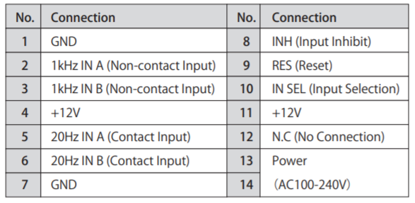
How to use BCD input
G90/95-303 as a totalizer with free-write function
– DIP switch No.3 = OFF
– When reset is done, the value of the setting unit (model: PU-06-001) is shown on G90/95-303, instead of 0 (zero).
G90/95-303 as a large display
– DIP switch No.3 = ON
– Value on the setting unit (model: PU-06-001) is shown on G90/95-303.
If you use a setting unit made by another company, please confirm its output specifications.
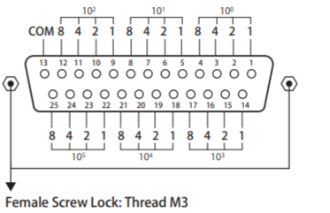
Pin Assignment G90 / G95-303 (BCD Input)
25-Pin D-Sub (DB25) Female Connector
* 25-Pin D-Sub (DB25) Male Connector is included
Setting Unit (Model: PU-06-001)
The value set on the digital switch of the setting unit will be shown on the large display (G90-303 or G95-303).
The connector for wiring to the large display (G90-303 or G95-303) is included but the straight cable available in the market can be used.

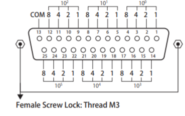
Pin Assignment G90 / G95-303 (BCD Input)
25-Pin D-Sub (DB25) Female Connector
* 25-Pin D-Sub (DB25) Male Connector is included
Dimensions (mm)
G90 Series
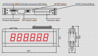
G95 Series
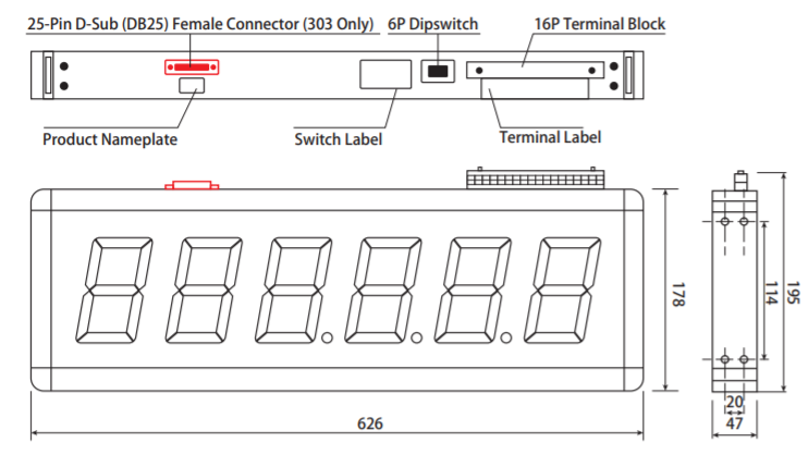
Accessories
1. Hanging Bracket (Left)
2. Hanging Bracket (Right)
3. Base-mounting Bracket
4. Allen Screw
5. Spring Washer
6. 25-Pin D-Sub (DB25)
Male Connector (G90 / 95-303 Only)
7. Instruction Manual
Related Products
-
Niigata Seiki AG-22 Angle Gauge
-
Hasegawa Electric HXA-6S Type Hot Line Proximity Detector Exclusively For Overhead Line Works
-
Yamayo DTM-15 Digital Body Measure & MM-15 Body Measure
-
Niigata Seiki SET STEEL RING GAUGE
-
Niigata Seiki CCTPG-715A/ CCTPG-715B Circular Taper Gauge with Green Color Case
-
KETT ELECTRIC LABORATORY KJT-CNT2 Controller


