Electronic Counters, Japan, Line Seiki, Measurement
Line Seiki MDR Series Digital Counter (Totalizer)
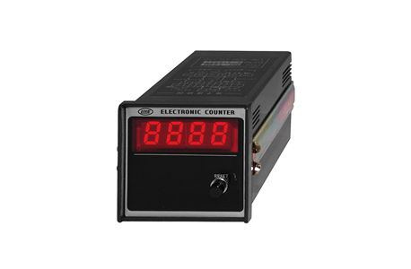
Product Made in Japan
Manufacturer: Line Seiki
Model: MDR Series (Totalizer)
MDR Series Totalizer
Model
| Models | Digits | Memory | Weight |
| MDR-040M | 4 | O | 530 grams |
| MDR-060M | 6 | O |
Description
The MDR (Totalizer) Series is a 4 or 6-digit LED bi-directional totalizer in a DIN 72 x 72-panel size (Panel Cut-out size: 68 x 68mm). This is a very simple but functional totalizer with a high count speed of 5kHz maximum. This bi-directional counter accepts Contact or Non-Contact pulse input and count modes includes Add/Subtract or Quadrature. The MDR (Totalizer) Series can be powered by AC100/110V or AC200/220V, selectable, and it has an external power supply of DC12V for sensors. It has push-button reset on the front panel and remote reset is also available. Memory is built-in for retention of count values during power loss of the counter.
Specification
| Models | MDR-040M | MDR-060M |
| Display | Red LED, 14.22 x 8.13mm (Zero Suppress) | Red LED, 10.16 x 5.54mm (Zero Suppress) |
| Input Method / Signal | Contact Input: Relay, Microswitch Non-Contact Input : L : 0 – 1V ; H : +4.5 – 27 | |
| Count Mode | 90°Quadrature (directional) / Add/Subtract | |
| Count Speed | Contact Input : 20 Hz max. / Non-Contact Input : 5000 Hz max. | |
| Pulse Width | Contact Input : 25 msec min. / Non-Contact Input : 100 msec min. | |
| Make (Duty) | 1 : 1 | |
| Reset | Front reset (push button) Remote reset (100msec min.) | |
| Memory | E²PROM (10 years. retention, 10,000 times) | |
| Power Source for Sensor | DC12V 50mA maximum | |
| Input Impedance | 5kΩ | |
| Power Source | AC100/110V or AC200/220V ±10%, 50/60 Hz | |
| Power Consumption | Approximately 3.5VA | |
| Operating Temperature | 0 – 40°C (non-freezing) | |
| Operating Humidity | 45 – 85% RH (non-condensing) | |
| Hi-pot Test | AC1500V (1 minute) | |
| Dielectric Test | 20MΩ min. (DC500V megger) | |
| Connection | M3 Terminal Screw | |
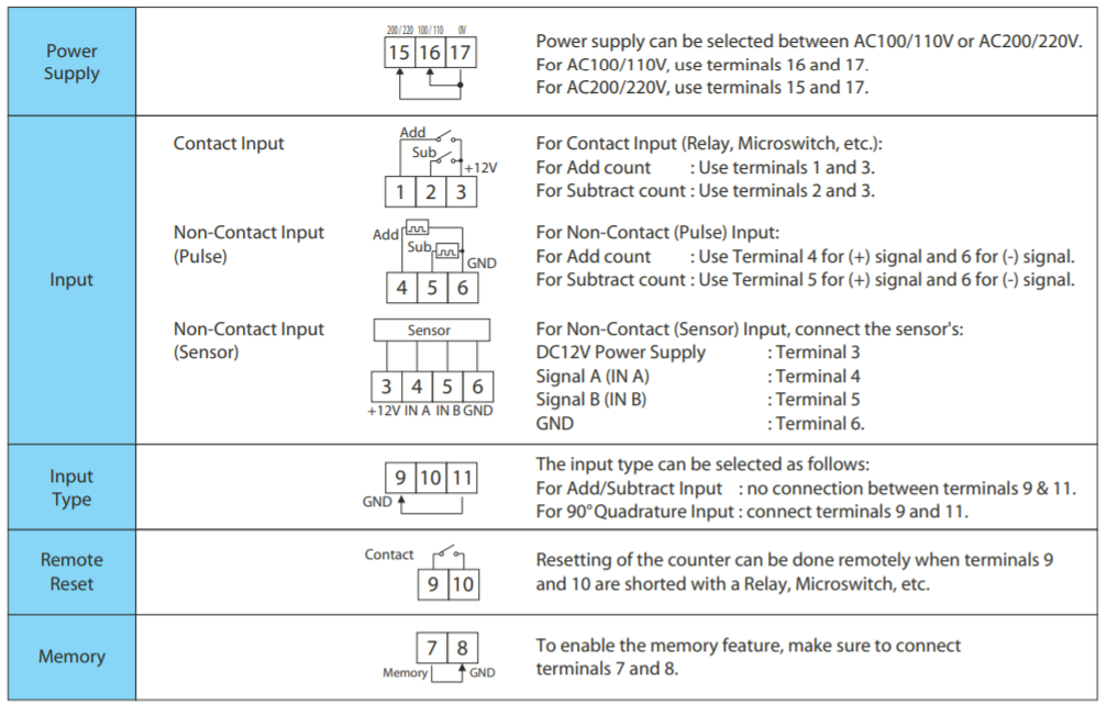
Rear Terminals And Wiring

Connection
Caution
1. Do not feed a voltage signal into the Contact Input and Remote Reset terminals. This may cause damage to the internal circuit of the unit.
2. Contact and Non-contact input cannot be used simultaneously. Please choose only one method of input.
3. During a power failure, the LED display will go off. At this time, the counter cannot detect input or reset signals even if signals are received.
4. Make sure to short terminals 7 and 8 to enable the memory function. When the counter will be shut down for a long period of time, disconnect terminals 7 & 8 to prevent the discharge of the internal battery. The internal battery is charged when power is supplied to the counter.
5. Simultaneous input of signals for the Add input and Subtract input is not possible. Use a multiplexer (ex. PS-41S) if such function is desired.
6. Use shielded lead wires for the Input terminal and Reset terminal. Also, make the lines from the power source as far as possible from the lines of the Input and Reset lines.
Related Products
-
Satuma Denki BMS5-T, BMS5-WT Lifter Brakes MEW
-
Vessel No.HPB-810 High Power Ionizing Bar
-
Ascon BR1-6T-202 (suction type) Index w/ Material Handling Indexing table automatic machine Blast Cabinet
-

Kamoi Kakoshi Mint Wallpaper For Gypsum Board
-
IMADA SDT series Rotation Support Jig for DTXS/A
-
Chiyoda Seiki Cardle Production Copper Pipe Connecting Pipe Teflon Flexible Hose


