Drilling And Cutting, Hand Tools, Japan, Miyakawa
Miyakawa C Type Circular Holder Multi-axis Drill
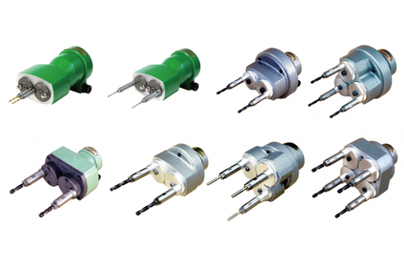
Product Made in Japan
Manufacturer: Miyakawa
Model: C-63, C-64, C-86 Type 2 axes, C-86 Type 3 axis, C-108 type 2 axis, C-110 type 2 axis, C-110 type 3 axis, C-110 type 4 axis
C-63 (pitch between 2 axis 8 mm – 64 mm)
Overview
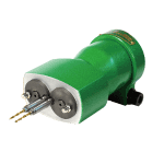 | 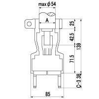 |  A: outer diameter of main shaft quill diameter A: outer diameter of main shaft quill diameterC: length of main shaft end F: size of JT |
Performance specification
| Model used Drilling machine | 多軸アタッチメント・R面取り機の宮川工業|岐阜県関市 (miyakawa.com) |
| Screw used | 多軸アタッチメント・R面取り機の宮川工業|岐阜県関市 (miyakawa.com) |
| Model | 2C-J63 |
| Types of chucks | C-3 |
| Maximum spindle speed (RPM) | 3000 |
| Maximum axial distance (mm) | 64 |
| Minimum axis distance between two axes (mm) | 8 |
| Drilling ability per axis S45C (mm) | 3 |
| Screw standing capacity per axis S45C (M) | 2.6 |
| Maximum clamp diameter of chuck (mm) | 3 |
| Weight (kg) | 1.5 |
Overview
C-64 (pitch between 2 axis 10 mm – 64 mm)
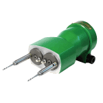 | 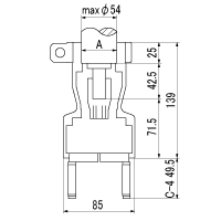 |  A: outer diameter of main shaft quill diameter A: outer diameter of main shaft quill diameterC: length of main shaft end F: size of JT |
Performance specification
| Model used Drilling machine | 多軸アタッチメント・R面取り機の宮川工業|岐阜県関市 (miyakawa.com) |
| Screw used | 多軸アタッチメント・R面取り機の宮川工業|岐阜県関市 (miyakawa.com) |
| Model | 2C-J64 |
| Types of chucks | C-4 |
| Maximum spindle speed (RPM) | 3000 |
| Maximum axial distance (mm) | 64 |
| Minimum axis distance between two axes (mm) | 10 |
| Drilling ability per axis S45C (mm) | 4 |
| Screw standing capacity per axis S45C (M) | 3 |
| Maximum clamp diameter of chuck (mm) | 4 |
| Weight (kg) | 1.5 |
C-86 type 2 axis (pitch between 2 axis 16 mm – 86 mm)
Overview
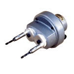 | A: Outer diameter of main shaft quill diameter B: Outer diameter of main shaft C: Length of main shaft end D: Outer diameter of flange of main shaft quill E: Thickness of flange of main shaft quill F: JT or MT number | J Jacobs taper | M Morse taper | M Morse taper |
Performance specification
Dimensional drawing
| 2C-J86 type | 2C – 2M86 type | 2C – 3M86 type |
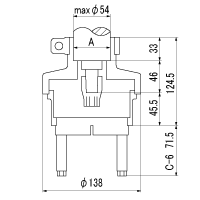 | 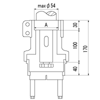 | 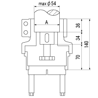 |
| The dimensions in the above figure are part of an attachable drilling machine and screw spindle. Detailed dimensions regarding actual model to be installed may be different, so please contact our service center. | ||
C-86 type 3 axes (pitch between 2 axes 28 mm – 98 mm)
Overview
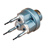 | Features
| 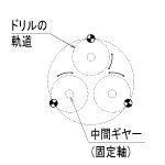 |
Performance specification
Dimensional drawing
| 3C-J86 type | 3C-2M86 type | 3C – 3M86 type |
 |  |  |
| The dimensions in the above figure are part of an attachable drilling machine and screw spindle. Detailed dimensions regarding actual model to be installed may be different, so please contact our service center. | ||
C-108 type 2 axes (pitch between 2 axes 25 mm – 108 mm)
Overview
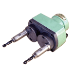 | A: Outer diameter of main shaft quill diameter B: Outer diameter of main shaft C: Length of main shaft end D: Outer diameter of flange of main shaft quill E: Thickness of flange of main shaft quill F: JT or MT number | J Jacobs taper | M Morse taper | M Morse taper |
Performance specification
Dimensional drawing
| 2C-J108 type | 2C – 2M108 type | 2C – 3M108 type |
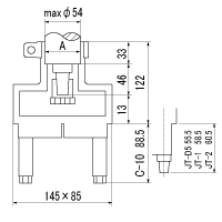 | 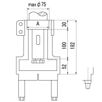 | 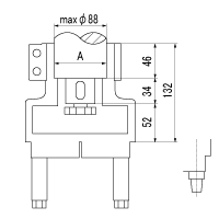 |
| The dimensions in the above figure are part of an attachable drilling machine and screw spindle. Detailed dimensions regarding actual model to be installed may be different, so please contact our service center. | ||
C-110 type 2 axes (pitch between 2 axes 26 mm – 110 mm)
Overview
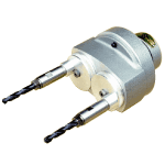 | A: Outer diameter of main shaft quill diameter B: Outer diameter of main shaft C: Length of main shaft end D: Outer diameter of flange of main shaft quill E: Thickness of flange of main shaft quill F: JT or MT number | J Jacobs taper | M Morse taper | M Morse taper |
Performance specification
Dimensional drawing
| 2C-J110 type | 2C – 2M110 type | 2C – 3M110 type |
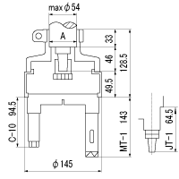 | 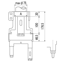 | 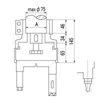 |
| The dimensions in the above figure are part of an attachable drilling machine and screw spindle. Detailed dimensions regarding actual model to be installed may be different, so please contact our service center. | ||
C-110 type 3 axes (pitch between 2 axes 38 mm – 122 mm)
Overview
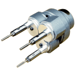 | Features
|  |
Performance specification
Dimensional drawing
| 3C-J110 type | 3C-2M110 type | 3C-3M110 type |
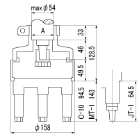 | 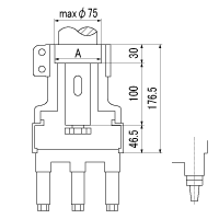 | 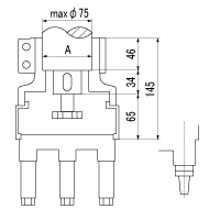 |
| The dimensions in the above figure are part of an attachable drilling machine and screw spindle. Detailed dimensions regarding actual model to be installed may be different, so please contact our service center. | ||
C-110 type 4 axes (pitch between 2 axes 58 mm – 142 mm)
Overview
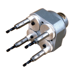 | Features
| 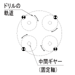 |
Performance specification
Dimensional drawing
| 4C-J110 type | 4C-2M110 type | 4C-3M110 type |
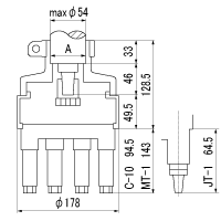 | 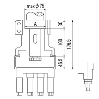 | 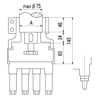 |
| The dimensions in the above figure are part of an attachable drilling machine and screw spindle. Detailed dimensions regarding actual model to be installed may be different, so please contact our service center. | ||
Related Products
-
Eagle Clamp FHA Type Shaped Steel Clamp
-
NAGANO KEIKI TH82 Temperature Transmitters
-
KONAN MS6810 Pneumatic Cylinder Lightweight Compact Oilless Enclosed With 5-port Solenoid Valve And Reed Switch
-
Naniwa Eye Nut
-
SAKUSAKU SDHR20120202 Holder For Grooving And Parting Off
-
SAKUSAKU DCGT11T304-AL Turning Insert 55° Rhombic/7° Positive


